


 BOM
BOM Cart
Cart Product Catalog
TB6612 motor driver is a key part of robotics and embedded systems. Microcontrollers such as Arduino cannot directly drive motors because motors require higher current than a microcontroller pin can provide. A motor driver IC acts as an interface between the control circuit and the motor. One widely used solution is the TB6612FNG IC, which offers efficient dual DC motor control in a compact package.
This article explains the TB6612 driver chip, its structure, pinout, features, Arduino motor driver module, comparison with other drivers, and example Arduino code.
1. What is the TB6612 Driver IC?
2. TB6612FNG Motor Driver Structure and Working Principle
3. TB6612 Pinout and Schematic Diagram
5. Arduino TB6612 Motor Driver Module Application
9. Frequently Asked Questions [FAQ]
What is the TB6612 Driver IC?
The TB 6612 is a dual H-bridge driver IC designed for controlling DC motors efficiently. It uses MOSFET output transistors with low ON-resistance, which minimizes power loss and heat generation. The IC receives two logic input signals, IN1 and IN2, for each motor channel, allowing selection of one of four operating modes: clockwise rotation (CW), counter-clockwise rotation (CCW), short brake, or stop (coast) mode. This flexibility enables precise motor direction and braking control. Compact and highly integrated, the chip widely use in Arduino projects, robotics, and small automation systems, providing reliable dual-motor control in a single IC.
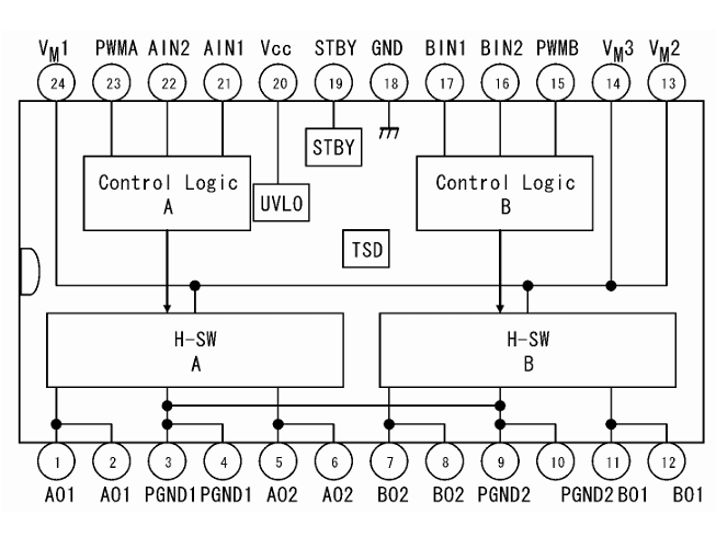
TB6612FNG Motor Driver Structure and Working Principle
The TB6612 FNG is a dual H-bridge motor driver IC, meaning it contains two independent H-bridge circuits, labeled Channel A and Channel B, which allow it to control two DC motors simultaneously. Each H-bridge consists of four MOSFET switches arranged as follows: two high-side MOSFETs and two low-side MOSFETs.
This arrangement controls the direction of current flow through the motor, determining whether the motor rotates clockwise, counter-clockwise, or stops. By combining logic inputs (AIN1/AIN2 for Channel A, BIN1/BIN2 for Channel B) and PWM signals (PWMA/PWMB), the TB6612FNG can regulate both motor speed and direction efficiently.
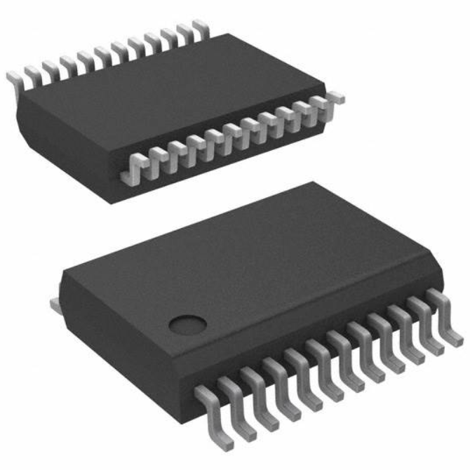
The IC also includes a STBY (standby) pin to enable low-power mode when motors are inactive, reducing energy consumption. Its compact 24-SSOP package allows integration into small robotics and embedded motor control systems, providing high efficiency, low heat, and precise dual-motor control.
Working Principle
The motor direction determine by the logic signals on IN1 and IN2 pins.
IN1 | IN2 | Motor Mode |
0 | 0 | Stop (coast) |
1 | 0 | Clockwise |
0 | 1 | Counter-clockwise |
1 | 1 | Short brake |
PWM signals applied to PWMA or PWMB control the motor speed.
The STBY (standby) pin enables or disables the driver:
· STBY = High → Normal operation
· STBY = Low → Low-power standby mode
This structure allows efficient motor control using only a few control signals from a microcontroller.
TB6612 Pinout and Schematic Diagram
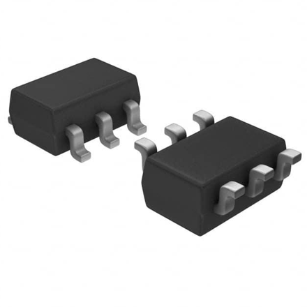
The TB6612FNG typically package in a 24-pin SSOP package.
TB 6612 Pin Description
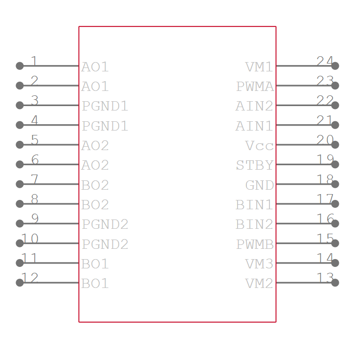
No. | Pin Name | I/O | Function |
1 | AO1 | O | Channel A output 1 |
2 | AO1 | O | Channel A output 1 |
3 | PGND1 | — | Power ground |
4 | PGND1 | — | Power ground |
5 | AO2 | O | Channel A output 2 |
6 | AO2 | O | Channel A output |
7 | BO2 | O | Channel B output |
8 | BO2 | O | Channel B output |
9 | PGND2 | — | Power ground |
10 | PGND2 | — | Power ground |
11 | BO1 | O | Channel B output |
12 | BO1 | O | Channel B output |
13 | VM2 | — | Motor supply voltage |
14 | VM3 | — | Motor supply voltage |
15 | PWMB | I | Channel B PWM input |
16 | BIN2 | I | Channel B input 2 |
17 | BIN1 | I | Channel B input 1 |
18 | GND | — | Signal ground |
19 | STBY | I | Standby control |
20 | VCC | — | Logic supply |
21 | AIN1 | I | Channel A input 1 |
22 | AIN2 | I | Channel A input 2 |
23 | PWMA | I | Channel A PWM input |
24 | VM1 | — | Motor supply |
The AO1/AO2 and BO1/BO2 pins connect directly to the motors.
Schematic Diagram
TB6612 Feature
Power Supply Voltage
The TB 6612 supports a motor supply voltage (VM) up to 15V, making it compatible with most small DC motors and suitable for a wide range of robotics and embedded applications.
Output Current
It provides a continuous current of 1.2A and a peak current of 3.2A, delivering sufficient power for typical brushed and geared DC motors while ensuring reliable operation under load.
Low ON-Resistance
The IC uses MOSFET output transistors with a typical ON-resistance of 0.5Ω, minimizing power loss, reducing heat generation, and improving overall efficiency in motor control circuits.
Standby System
The STBY pin enables a low-power standby mode, reducing energy consumption when motors are idle and extending battery life in portable applications.
Motor Control Modes
It supports clockwise (CW), counter-clockwise (CCW), short brake, and stop modes, allowing precise control of motor direction and braking behavior in compact systems.
Protection Circuits
Built-in thermal shutdown and low-voltage detection circuits protect both the IC and connected motors, ensuring safe operation under abnormal conditions.
Compact Package
Packaged in a 24-SSOP with 0.65 mm lead pitch, the TB6612FNG is ideal for space-constrained PCBs, making it perfect for modern Arduino robotics and small embedded motor control projects.
Arduino TB6612 Motor Driver Module Application
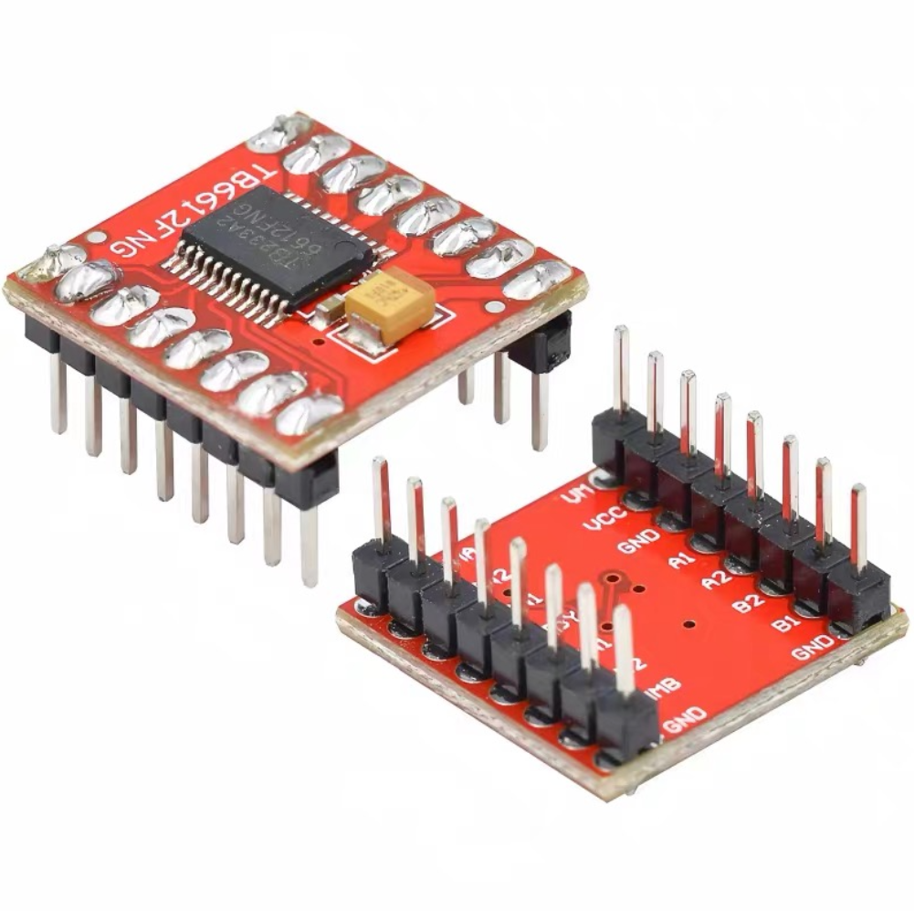
The TB6612 motor driver module is a high-efficiency, compact, and high-performance board designed for controlling two DC motors independently. It integrates the TB6612FNG IC with all necessary support components, providing stable motor control for Arduino and other microcontroller projects.
High Integration and Efficiency
The module is highly integrated, offering sufficient power output while keeping energy consumption low. Its design ensures reliable performance, even in small, compact motor control systems.
Powerful Motor Control
It can drive brushed and brushless DC motors, including high-speed and high-torque motors, making it suitable for robotics, automated vehicles, and embedded systems. Typical operating current is 1.2A per motor.
Control Pins
· AIN1 / AIN2, BIN1 / BIN2 – Control motor direction.
· PWMA / PWMB – PWM inputs for speed control.
· STBY – Standby or normal operation.
Output Pins
· AO1 / AO2 – Motor A output.
· BO1 / BO2 – Motor B output.
Power Supply
· VM (<10V) – Motor voltage input.
· VCC (2.7–5.5V) – Logic supply for Arduino or microcontroller control.
This module is ideal for Arduino-based robotics, smart vehicles, and compact motor control projects, offering precise speed and direction control in a small form factor.
TB6612 Arduino Sample Code
Here’s a simple Arduino example to control one DC motor using the TB6612FNG module. It demonstrates forward, reverse, and stop functions with PWM speed control.
// TB6612 Motor Driver Pin Definitions
#define AIN1 2 // Motor A input 1
#define AIN2 3 // Motor A input 2
#define PWMA 5 // Motor A PWM input
#define STBY 4 // Standby control pin
void setup() {
// Set pin modes
pinMode(AIN1, OUTPUT);
pinMode(AIN2, OUTPUT);
pinMode(PWMA, OUTPUT);
pinMode(STBY, OUTPUT);
// Enable TB6612 driver
digitalWrite(STBY, HIGH);
}
void loop() {
// Motor Forward
digitalWrite(AIN1, HIGH);
digitalWrite(AIN2, LOW);
analogWrite(PWMA, 200); // Speed control (0-255)
delay(2000);
// Motor Reverse
digitalWrite(AIN1, LOW);
digitalWrite(AIN2, HIGH);
analogWrite(PWMA, 200);
delay(2000);
// Motor Stop (Coast)
digitalWrite(AIN1, LOW);
digitalWrite(AIN2, LOW);
delay(2000);
// Short Brake
digitalWrite(AIN1, HIGH);
digitalWrite(AIN2, HIGH);
delay(2000);
}
Explanation:
· AIN1 / AIN2: Set motor direction.
· PWMA: Controls motor speed via PWM (0–255).
· STBY: Must be HIGH to activate the driver.
· AO1 / AO2: Connect to motor terminals.
Can easily extend this code to control a second motor using BIN1, BIN2, and PWMB.
TB6612FNG VS L298N
TB6612FNG
The TB6612FNG is a modern dual H-bridge motor driver IC that uses MOSFET output transistors with low ON-resistance, providing high efficiency and low heat generation. It can independently control two DC motors with four modes: clockwise, counter-clockwise, short brake, and stop. The IC operates with logic voltage 2.7–5.5V and motor supply 2.5–13.5V, delivering 1.2A continuous current and up to 3.2A peak. Its compact 24-SSOP package makes it ideal for Arduino projects, small robots, and integrated motor control systems, offering reliable dual-motor control in a small footprint.
L298N
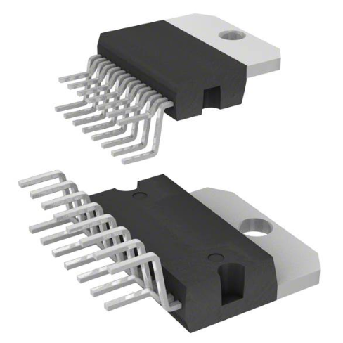
The L298N is an older dual H-bridge motor driver built using bipolar transistors in a through-hole 15-Multiwatt package. It supports higher motor supply voltages up to 46V and continuous current of 2A per motor, making it suitable for larger motors. However, the bipolar design has a higher voltage drop, which reduces efficiency and generates more heat, often requiring a heatsink. L298N supports standard motor control modes (CW, CCW, brake, and stop) and widely use in industrial applications or projects requiring higher voltage motors, but it is larger and less efficient than modern MOSFET-based drivers.
Feature | TB6612FNG | L298N |
Driver Type | MOSFET | Bipolar transistor |
Package | 24-SSOP | Multiwatt-15 |
Efficiency | High | Lower |
Voltage Range | 2.7V–13.5V | Up to 46V |
Continuous Current | 1.2A | 2A |
Size | Compact | Larger |
Heat Generation | Low | Higher |
Summary
TB6612FNG is smaller and more efficient, while L298N supports higher voltage but produces more heat.
DRV8833 vs TB6612
DRV8833
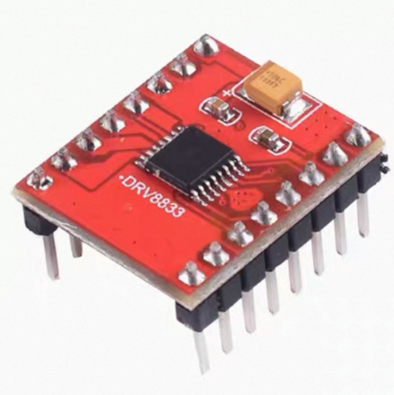
The DRV8833 is a dual H-bridge motor driver IC that uses NMOS transistors for PWM-controlled DC motor applications. Each H-bridge can deliver up to 1.5A output current, making it suitable for small to medium motors. It operates with a supply voltage of 2.7V to 10.8V and can drive motors within the same voltage range. The DRV8833 includes built-in protection features, such as overcurrent protection, short-circuit protection, undervoltage lockout, and thermal shutdown, and also supports a low-power sleep mode to conserve energy. It comes in a 16-TSSOP package, ideal for compact designs.
TB6612
The TB 6612 is a dual H-bridge motor driver IC designed for low-voltage, efficient motor control. It can handle a continuous output current of 1A and a peak current of 3.2A, with a motor voltage range of 2.5V to 13.5V and logic supply voltage of 2.7V to 5.5V. The operating temperature is -20°C to 85°C, making it reliable for small robotics and Arduino projects. Package in a 24-SSOP compact form, and supports four motor modes: clockwise, counter-clockwise, short brake, and stop, with PWM speed control.
Comparison Summary:
DRV8833 supports slightly higher continuous current (1.5A) and broader voltage supply.
TB6612 supports higher peak current and higher motor load voltage, making it suitable for motors needing brief high power bursts.
DRV8833 includes more extensive built-in protection (short-circuit, sleep mode), while TB 6612 is simpler but efficient.
Feature | DRV8833 | TB6612 |
Output Current | 1.5A | 1A |
Supply Voltage | 2.7V~10.8V | 2.7V~5.5V |
Load Voltage | 2.7V~10.8V | 2.5V~13.5V |
Protection | Overcurrent, thermal, UVLO | Thermal shutdown |
Package | 16-TSSOP | 24-SSOP |
Motor Control | Dual H-bridge | Dual H-bridge |
DRV8833 includes additional protection functions, while TB6612 offers higher load voltage support.
TB6612 Datasheet
The data sheet contains detailed information including:
· Electrical characteristics
· Timing diagrams
· Pin configuration
· Maximum ratings
· Application circuits
Engineers should review the datasheet when designing circuits to ensure proper operation.
Frequently Asked Questions [FAQ]
Why isn't the motor rotating?
The motor not rotate because incorrect wiring, insufficient motor supply voltage, or inactive STBY pin. Ensure AIN/BIN control signals and PWM inputs are correct, and properly connect the motor to the AO/BO output pins.
Why can a motor only rotate in one direction?
This usually occurs if AIN1/AIN2 or BIN1/BIN2 signals are not toggled correctly. Check wiring, confirm apply the logic levels properly, and ensure the STBY pin is HIGH, enabling motor rotation in both directions.
Can it drive a 12V/2A motor?
TB6612FNG supports 1.2A continuous and 3.2A peak current. A 12V/2A motor exceeds its safe continuous limit, which may cause overheating or shutdown, making it unsuitable for continuous 2A operation.
What is the difference between L298N and TB6612?
TB 6612 uses MOSFET H-bridges for high efficiency, low heat, and compact size, while L298N uses bipolar transistors, handling higher voltages but with more power loss, heat, and larger size.
What type of motor is best for TB6612FNG?
It works best with small brushed DC-motors, geared DC motors, and low-voltage motors common in Arduino robotics, smart cars, and embedded systems, supporting efficient forward, reverse, braking, and speed control.
How many motors can TB6612FNG control?
The TB6612FNG has two independent H-bridge channels, allowing it to control two DC motors independently or one bipolar stepper motor, providing flexible motor control in compact applications.
Conclusion
The TB6612 is a compact, efficient, and versatile dual H-bridge motor driver IC, ideal for Arduino projects, robotics, and small motor control systems. Its low ON-resistance MOSFETs ensure minimal heat and high efficiency, while PWM inputs allow precise speed and direction control.
Compared to older drivers like L298N, TB 6612 is smaller, more power-efficient, and easier to integrate. It supports two independent DC motors, multiple control modes (CW, CCW, brake, stop), and low-power standby operation, making it a reliable choice for compact, high-performance motor control applications.
With proper wiring and coding, it provides stable and precise motor control for a wide range of Arduino-based robotics projects.
Read More:
1. TP4056 Charging Module Pinout, Working, and Applications
HOT NEWS
The 0402 Resistor: A Comprehensive Guide
0402 Resistor
2025-05-06
Understanding A 0603 Resistor

0603 resistor,dimensions,marking code, values
2025-05-29
What Is A 1206 Resistor?
1206 resistor dimensions,footprint,value
2025-06-05
MT3608 Boost Converter - An In-Depth Guide
MT3608 Boost Converter
2025-09-04
What is 10k Ohm Resistor?
10k resistor 10k resistor color code
2025-05-14
Everything You Need To Know About ARE1309 Relay

2025-04-23
Complete Guide to the 220 Ohm Resistor
220 Ohm Resistor
2025-07-28
What is 100 Ohm Resistor And Color Code?

100 ohm resistor color code
2025-05-17
Guide To The AMS1117 Voltage Regulator
AMS1117 Voltage Regulator Circuit
2025-08-17
What Is The 1K Ohm Resistor?

1k ohm resistor and color code
2025-05-21