


 BOM
BOM Cart
Cart Product Catalog
A 470 ohm resistor is a passive component use in electrical and electronic circuits to limit the current that flows through a part of the circuit, set voltage levels, or protect sensitive components. 470 ohms is one of the common values and refers to its resistance — the opposition to the flow of electrical current, measured in ohm(Ω).
Color Code Reference Table
Colour | Digit | Multiplier | Tolerance | Temperature Coefficient |
Black | 0 | 1Ω | ||
Brown | 1 | 10Ω | ±1% | |
Red | 2 | 100Ω | ±2% | ±50ppm |
Orange | 3 | 1KΩ | ±15ppm | |
Yellow | 4 | 10KΩ | ±5ppm | |
Green | 5 | 100KΩ | ||
Blue | 6 | 1MΩ | ||
Violet | 7 | 10MΩ | ||
Grey | 8 | 0.001Ω | ||
White | 9 | 0.0001Ω | ||
Gold | - | 0.1Ω | ±5% | ±100ppm |
Silver | - | 0.01Ω | ±10% | ±250ppm |
No Band | ±20% | |||
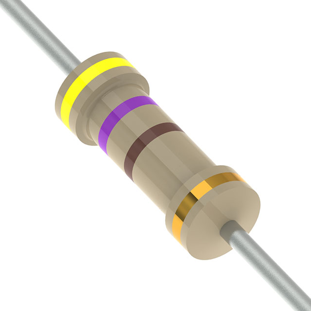
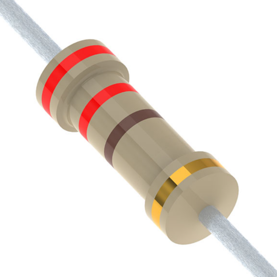
470 Ohm Resistors Color Code 4 band
Bands Number | Function | Colour | Value |
1 | 1st Digit | Yellow | 4 |
2 | 2nd Digit | Violet | 7 |
3 | Multiplier | Brown | X10 |
4 | Tolerance | Gold | ±5% |
1. 1st-Digit (Yellow)
· The 1st-band indicates the first significant digit of the resistance value. In this case, the color yellow corresponds to the number 4.
2. 2nd-Digit (Violet)
· The 2nd-band represents the second significant digit. The color violet corresponds to the digit 7. So far, we have the digits 4 and 7.
3. Multiplier (Brown)
· The 3rd-band indicates the multiplier, which is a factor by which the combined digits from the first and second bands will multiply. In this case, the color brown corresponds to a multiplier of x10. So, the digits 47 multiply by 10.
· This helps to scale the value of the circuit up or down to match the required resistance for the specific application. In this case, multiplying 47 by 10 gives the final value of 470Ω. This scaling factor makes the component versatile for different types of circuits requiring precision.
o Calculation: 47 × 10 = 470ohms
4. Tolerance (Gold ±5%)
· The 4th-band represents the tolerance, which indicates how much the actual resistance available from the labeled value. In this case, gold means the tolerance is ±5%.
Here are the commonly Range:
Tolerance | Range-Value(Ω) |
±0.02% | 469.9094~470.0906 |
±0.05% | 469.765~470.235 |
±0.1% | 469.53~470.47 |
±0.2% | 469.04~470.96 |
±0.5% | 468.15~471.85 |
±1% | 466.3~473.7 |
±2% | 460.6~479.4 |
±5% | 446.5~493.5 |
±10% | 423~517 |
±20% | 376~564 |
Example:
· A ±5% tolerance means that the actual resistance could from:
5% of 470Ω = 23.5Ω
The actual resistance can between:
470Ω - 23.5Ω = 446.5Ω
470Ω + 23.5Ω = 493.5Ω
So, can be anywhere between 446.5ohms and 493.5ohms according to the ±5% tolerance.
If the resistor has more than four bands, the additional codes typically represent a precision tolerance or temperature coefficient, but for most basic resistors, the four colours cover the key information.
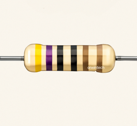
470 Ohm Resistor Color Code 5 Band
Band Number | Function | Colour | Value |
1 | 1st Digit | Yellow | 4 |
2 | 2nd Digit | Violet | 7 |
3 | 3rd Digit | Black | 0 |
4 | Multiplier | Black | x 1 |
5 | Tolerance | Gold | ±5% |
Total Resistance:470 × 1 = 470Ω | |||
A 5-band with Yellow-Violet-Black-Black-Gold = 470Ω with ±5% tolerance.
Each band on a resistor has a specific purpose that helps define its resistance value and tolerance. Here’s a breakdown of what each band represents:
In a 5-band with a Black multiplier, the value would multiply by 1 (since Black represents x1).
It introduces an additional digit and multiplier, which allows for greater precision compared to a 4-band . Here's a breakdown of the colour and their meanings :
1. 1st-Digit (Yellow)
· The 1st-band represents the first significant digit, which in this case is 4.
2. 2nd-Digit (Violet)
· The 2nd-band is the second significant digit, which in this case is 7. So, the first two digits of the resistor's value are 47 (from Yellow and Violet).
3. 3rd-Digit (Black)
· The 3rd-band corresponds to the third significant digit. The color black represents the number 0, which makes the first three digits 470.
4. Multiplier (Black x1)
· The 4th-band is the multiplier. In this case, the color black indicates a multiplier of x1, meaning the value of the first three digits 470 multiply by 1, leaving the final resistance value as 470 ohms.
5. Tolerance (Gold±5%)
· The 5th-band represents the tolerance. The color gold indicates that the resistor's actual value can by ±5% from the nominal value.
Why is the 5-Band Resistor Important?
The 5-band is typically use for higher precision applications, where need a more accurate resistance value. The extra band (third significant digit) and the specific multiplier allow for more precise resistance values, especially in circuits where need to minimize tolerance .
1. Increased Precision:
The primary advantage of the 5-band code over the 4-band code is the additional digit and multiplier. This makes it ideal for more precise designs, where smaller variations in resistance are critical. For example, in sensitive analog circuits, 470 Ω might need to be a precise value for proper voltage or current regulation.
In a 4-band , the value of the resistance derive from only two significant digits (e.g., 47 and the multiplier), which limits its precision. The 5-band resistors, with three significant digits (e.g., 470), provides a finer granularity of resistance for more accurate applications.
2. Accurate and Flexible for Various Designs:
The third digit (black = 0) allows for more flexible design choices, particularly when you need exact resistance for tasks like voltage division, filtering, or current limiting in complex circuits. This is necessary in precision measuring equipment, high-frequency circuits, or audio electronics where even slight variations can affect performance.
Comparison: 4-Band vs. 5-Band Resistor
Feature | 4-Band-Resistor | 5-Band-Resistor |
Significant Digits | 2 digits (e.g., 47) | 3 digits (e.g., 470) |
Multiplier | Multiplier (x10) | More precise multipliers (x1) |
Tolerance | ±5%, ±1%, ±0.5%, etc. | ±5%, ±1%, ±0.5%, etc. |
Precision | Less precise | More precise |
Application | General purpose | High precision tasks (e.g., measurement, audio) |
Resistor 470 Ohm Color Code 6-Band
The breakdown would be:
Band Number | Function | Colour | Value |
1st | 1st Digit | Yellow | 4 |
2nd | 2nd Digit | Violet | 7 |
3rd | 3rd Digit | Black | 0 |
4th | Multiplier | Black | × 1 |
5th | Tolerance | Gold | ±5% |
6th | Temperature Coefficient | Any | See Below |
Total Resistance: 470 × 1 = 470Ω ±5% | |||
Temperature Coefficient (6th-Band):
This bands-code indicates how the resistance will change with temperature (in ppm/°C). Here are the typical color :
Colour | Temperature Coefficient (ppm/°C) |
Silver | ±250ppm/°C |
Gold | ±100ppm/°C |
Red | ±50ppm/°C |
Orange | ±15ppm/°C |
Yellow | ±5ppm/°C |
470Ω with a six-band color code:
(Yellow-Violet-Black-Black-Gold-Gold)
with ±5% tolerance ±100ppm/°C temperature.
4 vs 5 vs 6 Bands
Band Number | four-Band | five-Band | six-Band |
1st | Yellow (4) | Yellow (4) | Yellow (4) |
2nd | Violet (7) | Violet (7) | Violet (7) |
3rd | Multiplier | Black (0) | Black (0) |
Brown (×10) | |||
4th | Tolerance | Multiplier | Multiplier Black (×1) |
Gold (±5%) | Black (×1) | ||
5th | - | Tolerance | Tolerance |
Gold (±5%) | Gold (±5%) | ||
6th | - | - | Temperature Coefficient Any |
4-Band: Standard 470Ω ±5% with Yellow-Violet-Brown-Gold.
5-Band: More precise 470ohm ±5% with Yellow-Violet-Black-Black-Gold.
6-Band: Same 470ohms ±5% with an additional temperature coefficient for higher precision and temperature stability.
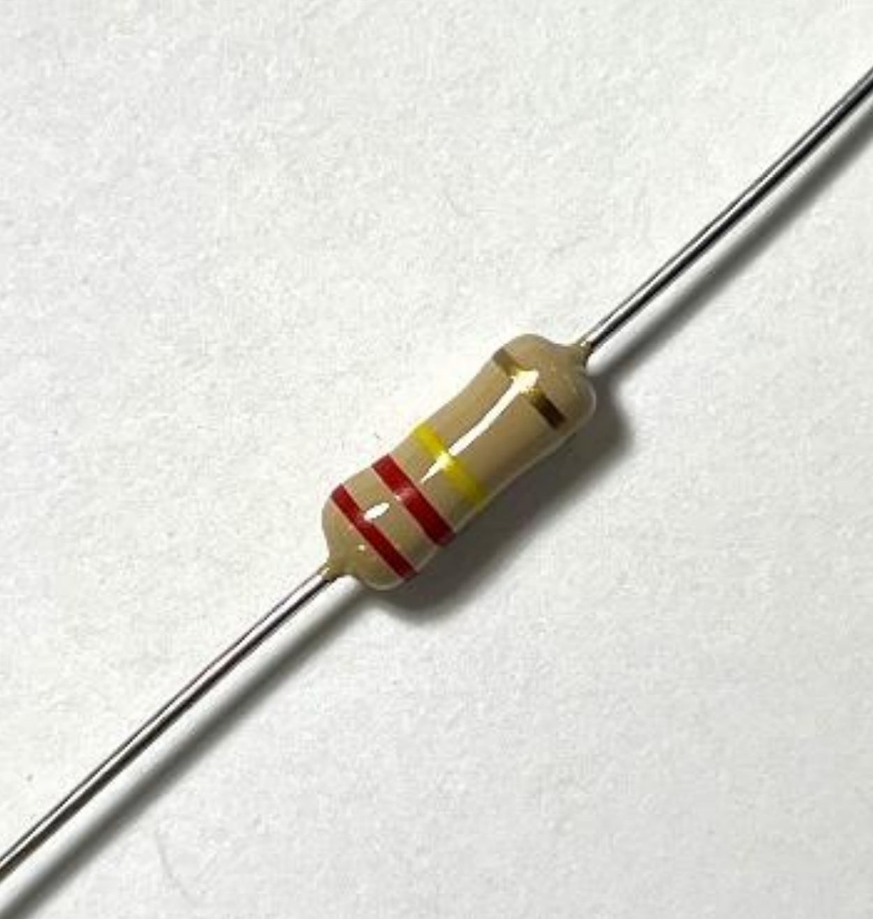
How to Read the code for 470R resistors?
To read for this circuit, you need to decode the colored bands on it. Here's a step-by-step guide:
With four-Bands:
First-Band (Yellow) represents the first digit is 4. Second-Band (Violet) represents the second digit is 7. Third-Band (Brown) is the multiplier ×10. Fourth-Band (Gold) is the tolerance means ±5%.
So, for a 4-band 470R-resistor, the number formed by the first two digits (4 and 7) is 47, the 3rd-band is a multiplier of ×10, so 47 × 10 = 470 R.
With 5 Bands (More precise):
1st-(Yellow): 4, 2nd-(Violet): 7, 3rd-(Black): 0, 4th-(Black): Multiplier ×1, 5th-Band (Gold) Tolerance ±5%.
So, for a 5-band 470R-resistor ,the number is 470 (4, 7, 0), the multiplier is ×1.
With 6 Bands (Including Temperature Coefficient):
1st-(Yellow): 4 ,2nd-(Violet): 7 ,3rd-(Black): 0 ,4th-(Black): ×1, 5th-(Gold): ±5% tolerance ,6th- (Red) indicates the temperature coefficient, typically 100 ppm/°C.
Power Rating(Wattage)
Indicate how much power they can dissipate safely without burning up. The different power ratings depending on the application.
0.05W(1/20W) | 0.5W(1/2W) | 3W | 10W |
0.063W(1/16W) | 0.6W | 3.25W | 11W |
0.1W(1/10W) | 0.75W(3/4W) | 3.75W | 13W |
0.125W(1/8W) | 1W | 4W | 13.5W |
0.167W(1/6W) | 1.2W | 5W | 14W |
0.2W(1/5W) | 1.5W | 5.25W | 15W |
0.25W(1/4W) | 1.7W | 6.5W | 16W |
0.3W | 1.75W | 7W | 17W |
0.333W(1/3W) | 2W | 8W | 20W |
0.4W | 2.25W | 9W | 40W |
Applications
Commonly use in a variety of electronic applications because its moderate resistance value. Here are some typical uses:
1. Current Limiting
· LED Circuits: Use to limit the current flowing through the LEDs. This prevents it from burning out because excess current.
o For example, in a 5V circuit with a standard LED (with a forward voltage of 2V), the 470 ohm resistors helps maintain a safe current (around 6.38mA).
2. Voltage Divider Circuits
· Use alongside other resistors to scale down the voltage to a desired level. Often use in signal processing and sensor circuits where you need to obtain a proportional voltage from a higher voltage source.
3. Signal Filtering (RC Circuits)
· Use in combination with capacitors to create RC (resistor-capacitor) filters. These filters use to smooth out signals in power supplies, audio systems, or signal processing to remove noise or unwanted frequencies.
4. Biasing Transistors
· In biasing circuits for transistors (in amplifiers or oscillators), used to set the correct operating point for the transistor, ensuring it works within its ideal range.
5. Pulse-Width Modulation (PWM)
· Use to control the timing of the pulses or the behavior of the circuit in generating a duty cycle. Useful in controlling the speed of motors or adjusting the brightness of LEDs.
6. Pull-up or Pull-down Resistor
· In combination with logic gates or microcontrollers to ensure that the input voltage stays at a defined level (either high or low). It's particularly use for debouncing buttons or switches.
7. Audio Circuits
· Use to limit the audio signal levels, preventing distortion or damage to sensitive components like speakers or audio processors.
8. Power Supply Circuits
· Use in combination with other components like zener diodes to help stabilize voltage output.
9. Timing Circuits
· Use (e.g., with capacitors in 555 timer circuits) to set the timing intervals in oscillators, pulse generation, or frequency generation.
10. Testing and Prototyping
· Use to quickly set up test circuits, especially when experimenting with basic components like LEDs, transistors, and microcontrollers.
Common Components Along with 470 Ohms Resistor:
· LEDs: To control current
· Capacitors: In RC filters or timing circuits
· Transistors: In biasing and amplification circuits
· Microcontrollers: For signal processing or digital logic
FAQ of 470 Resistor
1.What color resistor is 470 ohms?
A 470-ohm with a 4-band colour code typically has the following colors:
· First- (Digit 1): Yellow (4)
· Second- (Digit 2): Violet (7)
· Third- (Multiplier): Brown (x 10)
· Fourth- (Tolerance): Gold (±5%)
For a 5-band code:
· 1st- (Digit 1): Yellow (4)
· 2nd- (Digit 2): Violet (7)
· 3rd- (Digit 3): Black (0)
· 4th- (Multiplier): Black (x 1)
· 5th- (Tolerance): Gold (±5%)
For a 6-band colour code are:
· 1st- (Digit 1): Yellow (4)
· 2nd- (Digit 2): Violet (7)
· 3rd- (Digit 3): Black (0)
· 4th- (Multiplier): Black (x 1)
· 5th- (Tolerance): Gold (±5%)
· 6th- (Temperature Coefficient): Brown (100 ppm/°C)
So, the value is still 470 ohms, with a tolerance of ±5% and a temperature coefficient of 100 ppm/°C (indicating how much the resistance value changes with temperature).
2.What can I use instead of a 470 ohm resistor?
To replace a 470-ohms , you can use a 560-ohm for slightly higher resistance, reducing current flow. A 430-ohm will offer lower resistance, allowing more current. For adjustable resistance, a 500-ohm potentiometer works well, as it allows fine-tuning around 470 ohms. Alternatively, combine resistors in series or parallel: two 470-ohm resistors in series will give 940 ohms, while two 940-ohm resistors in parallel will result in 470 ohms. The right choice depends on your circuit's needs, whether it’s current regulation or a close approximation.
Read More:
1. 3.3 Ohm Resistor And Color Code
HOT NEWS
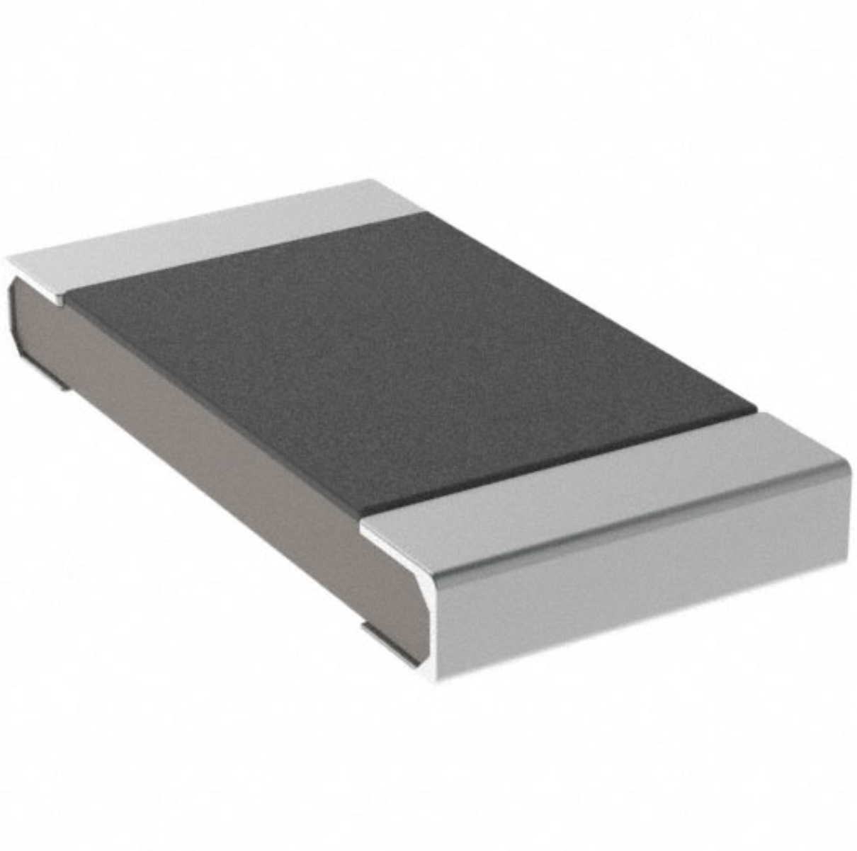
Understanding A 0603 Resistor
0603 resistor,dimensions,marking code, values
2025-05-29
The 0402 Resistor: A Comprehensive Guide
0402 Resistor
2025-05-06
LR41 Battery Guide: Specifications, Equivalents, and Uses
LR41 Battery Specifications, Equivalents, and Uses
2025-12-14
MT3608 Boost Converter - An In-Depth Guide
MT3608 Boost Converter
2025-09-04
What Is A 1206 Resistor?
1206 resistor dimensions,footprint,value
2025-06-05
TP4056 Charging Module Pinout, Working, and Applications
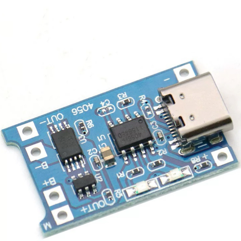
TP4056 Charging Module Pinout, Working, and Applications
2026-01-23
Everything You Need To Know About ARE1309 Relay
2025-04-23
Complete Guide to the 220 Ohm Resistor
220 Ohm Resistor
2025-07-28
120 Ohm Resistor- Specifications, Applications, and Features
2025-05-12
Guide To The AMS1117 Voltage Regulator
AMS1117 Voltage Regulator Circuit
2025-08-17