


 BOM
BOM Cart
Cart Product Catalog
The CD4051 is an analog multiplexer and demultiplexer IC, its ability to channelize and switch analog, the digital signals with high efficiency. Whether you're working with analog-to-digital or digital-to-analog conversion, or simply need to switch multiple signals between circuits, the CD4051 is for a variety of applications. Let’s dive into its datasheet description, pinout, and some frequently asked questions (FAQs) about this IC.
How the CD4051 IC Works
Work by allowing the user to select one of the 8 input/output channels (CH0 to CH7) and connect it to the COM (common) pin. The channel selection using three control pins (A, B, C), which are binary encoded. Base on the binary values of these control pins, the IC determines which channel connect to the common pin.
Channel Selection Example:
· If A = 0, B = 0, C = 0, CH0 connect to the COM pin.
· If A = 1, B = 0, C = 1, CH5 connect to the COM pin.
The INH (Inhibit) pin, when set LOW, disables all channels, and the COM pin becomes isolated.
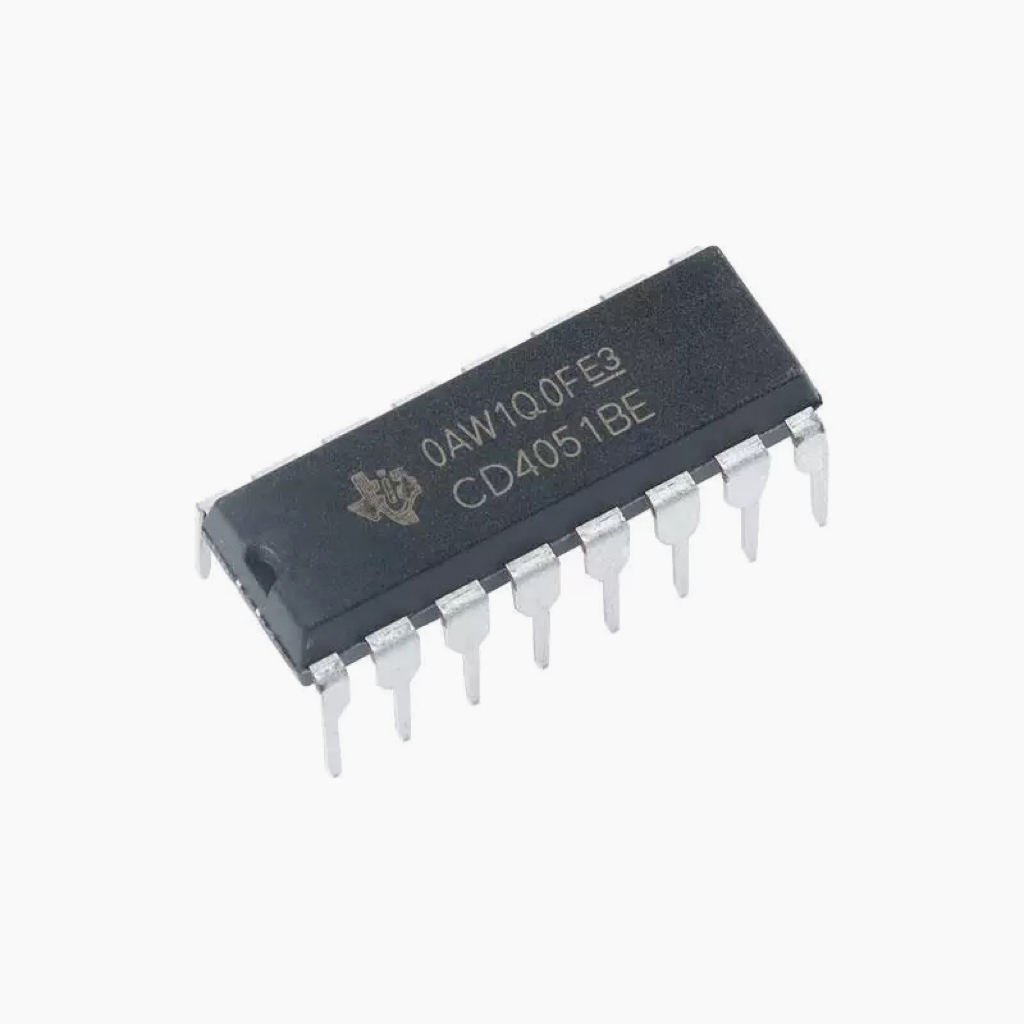
CD4051 Pinout
Pin No. | Pin Name | Function |
1 | CH4 | Channel 4 (I/O) |
2 | CH6 | Channel 6 (I/O) |
3 | COM | Common I/O Pin |
4 | CH7 | Channel 7 (I/O) |
5 | CH5 | Channel 5 (I/O) |
6 | INH | Inhibit Pin (Disables all channels) |
7 | VEE | Negative Power Input (optional) |
8 | VSS | Ground (0V) |
9 | C | Channel Select C (Control Pin) |
10 | B | Channel Select B (Control Pin) |
11 | A | Channel Select A (Control Pin) |
12 | CH3 | Channel 3 (I/O) |
13 | CH0 | Channel 0 (I/O) |
14 | CH1 | Channel 1 (I/O) |
15 | CH2 | Channel 2 (I/O) |
16 | VDD | Positive Power Input |
I = input, O = output
IC CD4051 Datasheet Description
Key Features
1. Low Power Consumption: Operates with low quiescent power, making it ideal for energy-efficient designs.
2. High-Precision Switching: It offers low ON resistance and low OFF leakage current, ensuring that signal integrity maintain.
3. Wide Voltage Range: The IC can operate over a broad voltage range, from VDD - VSS to VDD - VEE, depending on the application needs.
4. 8 Channels: Can handle 8 individual channels (CH0 to CH7), allowing for high flexibility in signal routing.
Applications
Have several practical uses in both analog and digital circuits. Here are some common applications:
1. Analog and Digital Multiplexing and Demultiplexing:
· For routing multiple signals through a single channel. Such as signal switching, where you want to send different signals to a common destination without the need for physical switches or multiple wires.
2. Analog-to-Digital or vice versa Conversion:
· In converting analog signals, In systems where sensor data (analog) needs to process by a microcontroller or where digital data needs to convert into an analog signal for audio output, for instance.
3. Signal Gating:
· Use as a gate to control the flow of signals to different parts of the circuit.
4. Factory Automation:
· In automation systems where multiple sensors need to rout through a single controller.
5. Televisions and Consumer Appliances:
· TVs and consumer electronics often use multiplexers for channel selection or managing multiple inputs and outputs.
6. Audio Systems:
· Use when different audio channels need to switch in or out of the circuit without affecting sound quality.
7. Programmable Logic Circuits:
· For require dynamic switching of signals.
8. Sensor Applications:
· Use where multiple sensor signals need to read by a microcontroller through a single input pin.
CD4051 Circuit Diagram
Here’s a how the components works:
VDD (+5V)
|
|
+--|--+
| | CD4051
| |
CH0 ------| |
CH1 ------| |--- Common I/O (COM) ----- Arduino Pin
CH2 ------| |
CH3 ------| |
CH4 ------| |
CH5 ------| |
CH6 ------| |
CH7 ------| |
| |
+--|--+
|
VSS (GND)
In the diagram:
· CH0 to CH7: These are the 8 input/output channels.
· COM (Common Pin): This is where the signal read or output.
· The selection of channels control by the digital pins connect to A, B, and C of the circuit(the channel select pins).
· INH: The inhibit pin, use to disable all channels when active (LOW).
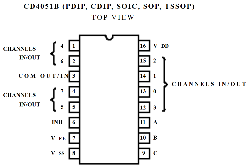
Control Arduino CD4051 multiplexer
To control this IC using an Arduino, you'll need to wire it up properly and use the Arduino's digital pins to select channels and control the input/output. Here's a step-by-step guide:
Here are the relevant pins for the CD4051:
· A (Pin 11), B (Pin 10), C (Pin 9): These are the channel select pins that determine which of the 8 channels (CH0 to CH7) are active.
· INH (Pin 6): This use to disable all channels (set to low to enable the channels).
· CH0 to CH7 (Pins 1,2,4,5,12~15): These are the channels that you can read from or write to, depending on your application.
· COM (Pin 3): This is the common input/output pin, where the signal is either read from or written to, based on the selected channel.
· VSS (Pin 8): Ground pin.
· VDD (Pin 16): Positive power input (usually +5V).
· VEE (Pin 7): Negative power input (can connect to ground if not using negative voltage).
Wiring the CD4051 to Arduino
1. Power Connections:
· VSS (Pin 8) to Ground on the Arduino.
· VDD (Pin 16) to 5V on the Arduino.
· VEE (Pin 7) to Ground (if not using negative voltage).
2. Channel Select Pins (A, B, C):
· A (Pin 11) → Connect to a digital pin on the Arduino (e.g., Pin 2).
· B (Pin 10) → Connect to a digital pin on the Arduino (e.g., Pin 3).
· C (Pin 9) → Connect to a digital pin on the Arduino (e.g., Pin 4).
3. Inhibit Pin (INH):
· INH (Pin 6) → Connect to Ground to enable the channels.
4. Channel Pins (CH0 to CH7):
· CH0 to CH7 : These are the input/output channels. You can either connect them to external devices or read/write signals.
5. Common Pin (COM):
· COM (Pin 3): This is the central pin for your analog signal (could be connected to an analog input/output on the Arduino).
Arduino Code Example
Here is a basic example to control the CD4051 using an Arduino:
int pinA = 2; // Channel select A
int pinB = 3; // Channel select B
int pinC = 4; // Channel select C
int commonPin = A0; // Analog input/output
void setup() {
pinMode(pinA, OUTPUT);
pinMode(pinB, OUTPUT);
pinMode(pinC, OUTPUT);
pinMode(commonPin, INPUT); // or OUTPUT to send a signal
Serial.begin(9600);
}
void loop() {
for (int i = 0; i < 8; i++) {
selectChannel(i); // Select a channel
delay(1000);
// Read analog signal from the common pin (optional)
int value = analogRead(commonPin);
Serial.print("Channel ");
Serial.print(i);
Serial.print(": ");
Serial.println(value);
}
}
void selectChannel(int channel) {
// Set the channel select pins based on the channel number
digitalWrite(pinA, (channel & 0x01) > 0); // A = bit 0 of channel
digitalWrite(pinB, (channel & 0x02) > 0); // B = bit 1 of channel
digitalWrite(pinC, (channel & 0x04) > 0); // C = bit 2 of channel
}
Explanation of Code:
· selectChannel(): This function sets the values of pins A, B, and C based on the channel you want to select.
· analogRead(): This reads the signal from the common pin (COM). You can change it to analogWrite() if you're using the common pin to send a signal.
· The loop goes through all 8 channels and reads from the common pin for each.
Additional Notes:
· If you're using the chips to switch analog signals, make sure the Arduino pin connect to the common pin (COM) is set to analog input (use analogRead()).
· To output an analog signal to the selected channel, you can use analogWrite() (for PWM output) on the common pin.
Frequently Asked Questions
About Analog Multiplexer CD4051 IC
1. What is CD4051?
The CD4051 is a high-performance analog multiplexer/demultiplexer design for low power consumption and high functionality. A digitally-controlled analog switch that allows multiple analog signals to rout to a common output or input. The chip can handle both analog and digital signals, and it supports up to 8 channels, giving you the flexibility to switch between multiple sources without needing multiple physical connections.
The CD4051 can work across a wide range of supply voltages, making it versatile for different designs, and it’s typically use in low power applications. To the low ON impedance and low OFF leakage current, the chip ensures minimal signal degradation when it's active and minimal signal interference when it's inactive.
2. What is the alternative to CD4051?
Some alternatives include the 74HC4051 , 74LS151 , MAX4617 , 74HC257 , 74HC4052 , ADG704 . These chips offer similar functionalities but vary in voltage ranges, power consumption, and switching speed. Choose the alternative based on your specific requirements (such as voltage, speed, or channel count).
Some commonly alternatives include:
1. 74HC4051
· Description: A high-speed CMOS analog multiplexer. Offering faster switching times.
· Key Features:
· 8-channel analog multiplexer.
· Operates with 5V logic levels.
· High-speed performance and lower ON resistance.
Difference: The 74HC4051 generally has faster switching capabilities and design for systems that require higher speed, making it ideal for digital electronics or faster analog switching.
2. 74LS151
· Description: A 8-channel multiplexer and demultiplexer. Part of the 74LS (Low Power Schottky) logic family and provides reliable signal routing with a slightly lower switching speed than the 74HC4051.
· Key Features:
· 8-channel analog/digital multiplexer.
· Available in low power Schottky logic.
· TTL compatible logic levels.
Difference: The 74LS151 has TTL logic compatibility and may not be as fast as the 74HC4051, but it widely use in TTL-based systems.
3. MAX4617
· Description: The MAX4617 is a low-voltage, single-pole, single-throw analog multiplexer with 4 channels. A higher-performance alternative that operates with low voltage (2V to 6V), and the brand Maxim Integrated.
· Key Features:
· 4-channel analog multiplexer (single-pole, single-throw).
· Works at low supply voltage (2V to 6V).
· Low ON resistance and low power consumption.
Difference: Offer fewer channels (4 vs 8 in the CD4051B), but more suitable for low-voltage applications.
4. 74HC257
· Description: The 74HC257 is an Octal Bus Switch that can also serve as a multiplexer for digital signal routing. A 3-state device, meaning it can control 8 digital channels for data bus applications.
· Key Features:
· 8-channel data bus multiplexer.
· High-speed CMOS technology.
· 3-state outputs (used for bus systems).
Difference: While the 74HC257 more focus on digital data bus applications, it could serve as an alternative in certain digital signal routing applications.
5. 74HC4052 (Dual 4-channel multiplexer)
· Description: Provide a dual 4-channel analog multiplexer instead of a single 8-channel multiplexer. Also part of the 74HC CMOS series.
· Key Features:
· Dual 4-channel multiplexer.
· Operates at 5V logic levels.
· Faster switching because its high-speed CMOS design.
Difference: The dual multiplexer (4 channels per block).
6. Analog Devices: ADG704
· Description: The ADG704 is a single-pole, single-throw (SPST) analog switch that works with 4 independent channels. Suitable for precision switching applications where require the low ON resistance and low leakage.
· Key Features:
· Low resistance and low leakage current.
· High-precision analog signal routing.
· Operates with 5V logic levels.
Difference: More emphasis on precision and signal integrity, but it only supports 4 channels instead of 8.
Summary of Substitutes:
· 74HC4051: Faster switching and higher speed; For high-speed applications.
· 74LS151: TTL-compatible; for older TTL-based designs.
· MAX4617: Lower voltage operation and low ON resistance; for battery-powered devices.
· 74HC257: Digital signal routing; for bus systems.
· 74HC4052: Dual 4-channel multiplexer; a compact alternative if you only need 4 channels.
· ADG704: High-precision analog switch; suitable for professional analog signal routing.
The best substitute for your project will depend on your voltage, speed, and channel-count requirements. If you need a faster, low-power alternative, the 74HC4051 or MAX4617 could be ideal. For TTL logic compatibility, the 74LS151 would be a good choice.
Feature | CD4051 | 74HC4051 | 74LS151 |
Channel Count | 8 | 8 | 8 |
Logic Family | CMOS | High-speed CMOS (HC) | Low Power Schottky (LS) |
Voltage Range | VDD = 3V to 18V | VDD = 2V to 6V | VCC = 4.75V to 5.25V |
Control Pins | A, B, C (3 pins) | A, B, C (3 pins) | A, B, C (3 pins) |
Power Consumption | Low quiescent power | Low quiescent power | Low power |
Switching Speed | Moderate speed | High-speed | Moderate speed |
ON Resistance | Low | Low | Moderate |
OFF Leakage Current | Low | Low | Low |
Applications | Signal multiplexing, ADC/DAC | High-speed signal routing | TTL-compatible signal routing |
Typical Use Case | Multiplexing, ADC/DAC | High-speed switching | TTL-based applications |
Feature | MAX4617 | 74HC257 | 74HC4052 | ADG704 |
Channel Count | 4 | 8 | 4 (dual 4-channel) | 4 |
Logic Family | CMOS | High-speed CMOS (HC) | High-speed CMOS (HC) | CMOS |
Voltage Range | 2V to 6V | VDD = 2V to 6V | VDD = 2V to 6V | 5V |
Control Pins | Control pins (2 or 3 pins) | A, B, C (3 pins) | A, B, C (3 pins) | Control pins (2 pins) |
Power Consumption | low quiescent power | Low quiescent power | Low quiescent power | Low power |
Switching Speed | High-speed, low resistance | High-speed | High-speed | High precision, low leakage |
ON Resistance | Low | Low | Low | Low |
OFF Leakage Current | Low | Low | Low | Low |
Applications | Low-voltage applications | Digital signal routing | Analog signal routing | Precision analog switching |
Typical Use Case | Battery-powered devices | Data bus applications | Analog signal switching | High-precision audio, sensor systems |
3. What is 4051 IC?
The 4051 IC refers to the CD4051, an analog multiplexer/demultiplexer IC that offers the capability to switch between 8 different analog or digital signals using control lines. This IC allows for the switching of multiple signals, both analog and digital, between multiple input/output channels and a common pin. Part of the 4000 series of ICs, for low power consumption and high functionality.
4. What is 74HC4051?
A similar IC to the CD4051(often refer to as 4051 IC), but the part of the 74HC (High-Speed CMOS). While it serves the same purpose, the 74HC4051 may offer faster switching and different power characteristics, making it more suitable for high-speed and better performance in digital systems.
Feature | 74HC4051 | CD4051 |
Speed | Higher speed (high-speed CMOS) | Lower speed (standard CMOS) |
Voltage Range | 2V to 6V | 3V to 18V |
Technology | High-speed CMOS | Standard CMOS |
Control Pins | A, B, C | A, B, C |
Power Consumption | Low | Low |
Application Focus | High-speed digital systems, audio, video | Analog signal multiplexing, general purpose |
The CD4051 use in electronics projects and systems where multiple analog or digital signals need to switch or rout.
Whether you're building a signal processing system, working on analog-to-digital conversion, or designing complex circuits, the CD4051 is a must-have in your electronics toolkit.
Read More:
HOT NEWS
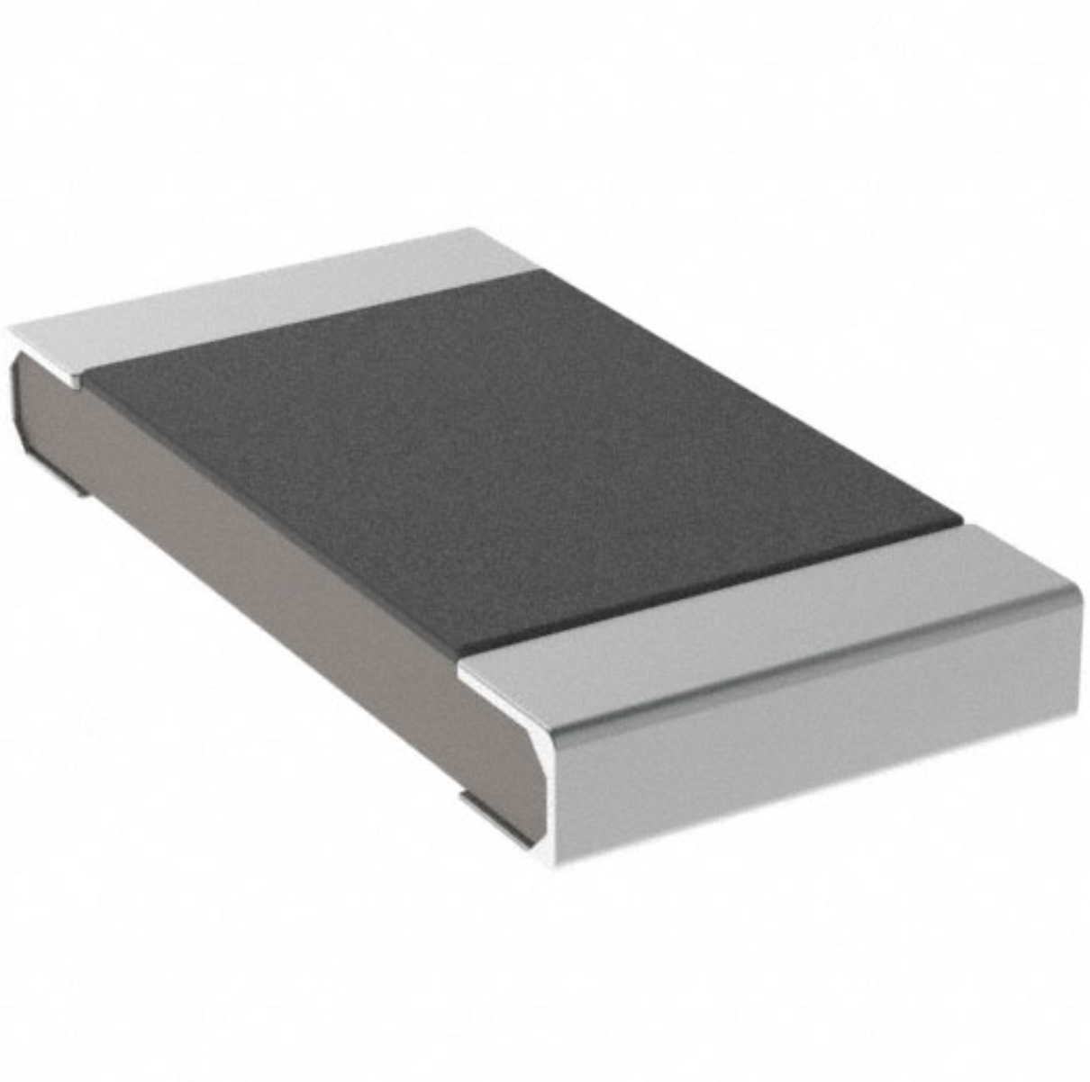
Understanding A 0603 Resistor
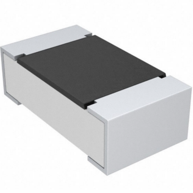
0603 resistor,dimensions,marking code, values
2025-05-29
The 0402 Resistor: A Comprehensive Guide
0402 Resistor
2025-05-06
LR41 Battery Guide: Specifications, Equivalents, and Uses
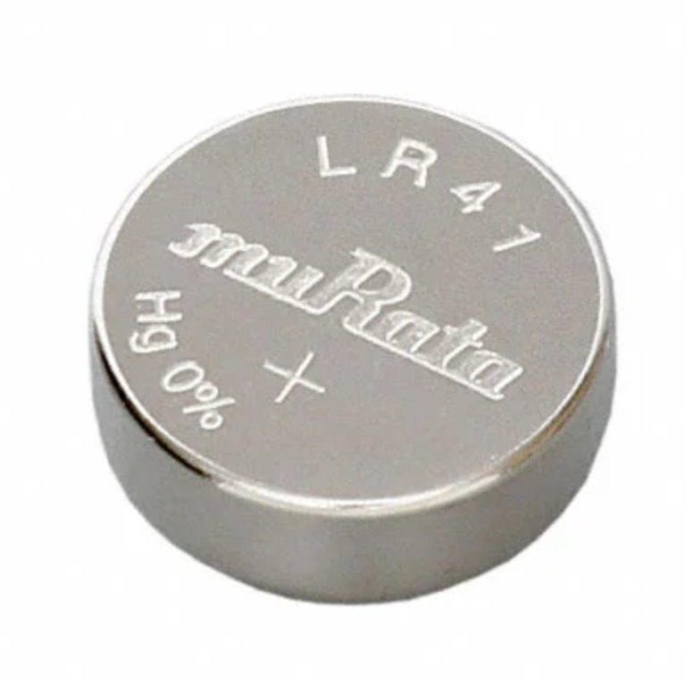
LR41 Battery Specifications, Equivalents, and Uses
2025-12-14
MT3608 Boost Converter - An In-Depth Guide
MT3608 Boost Converter
2025-09-04
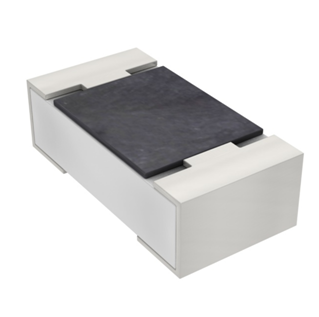
What Is A 1206 Resistor?
1206 resistor dimensions,footprint,value
2025-06-05
TP4056 Charging Module Pinout, Working, and Applications
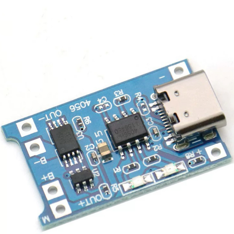
TP4056 Charging Module Pinout, Working, and Applications
2026-01-23
Everything You Need To Know About ARE1309 Relay
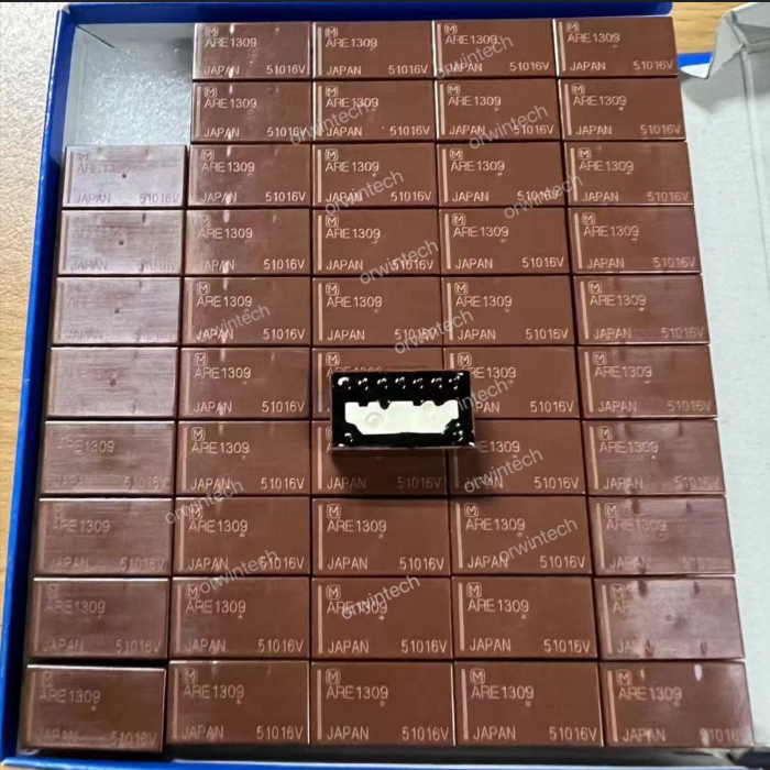
2025-04-23
Complete Guide to the 220 Ohm Resistor
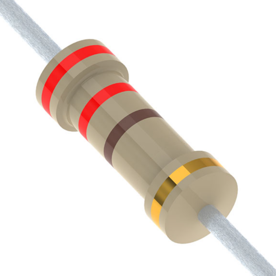
220 Ohm Resistor
2025-07-28
120 Ohm Resistor- Specifications, Applications, and Features
2025-05-12
Guide To The AMS1117 Voltage Regulator
AMS1117 Voltage Regulator Circuit
2025-08-17