


 BOM
BOM Cart
Cart Product Catalog
The ACS712 current sensor is a precise hall-effect-based current-sensing chip, design to measure both AC and DC currents in a variety of applications. With its high accuracy and ease of use, it is especially popular in industrial, automotive, and commercial systems, as well as in DIY projects. The sensor works by converting the magnetic field produced by the current flowing through a conductor into a proportional voltage that can measure by a microcontroller or other measuring instruments.
Whether you're working on motor control, load management, power supply systems, or overcurrent protection, the ACS712 offers an ideal solution for accurately monitoring current.
1. What is the ACS712 Current Sensor?
2. ACS712 Hall Effect Sensor Working Principle
3. Current Sensor ACS712 Features
5. Indirect Current Sensing with the ACS712 IC
6. Using ACS712 Current Sensor with Arduino
8. ACS712 5A Hall Effect Current Sensor Module Board
9. Frequently Asked Questions [FAQ]
What is the ACS712 Current Sensor?
The ACS712 is a fully integrated, hall-effect-based linear current sensor developed by Allegro Microsystems. Design to provide accurate and economical solutions for both AC and DC current sensing in various applications, including industrial, automotive, commercial, and communication systems. The sensor features 2.1 kVRMS voltage isolation and a low-resistance current conductor, making it ideal for use in high-voltage environments without the need for complex isolation techniques like opto-isolators.
The chip consists of a precise, low-offset hall sensor circuit paired with a copper conduction path. As current flows through this copper path, it generates a magnetic field, which detect by the integrated Hall IC. This magnetic field is then converted into a proportional voltage output, making it possible to accurately measure the current. The sensor's accuracy optimize by the proximity of the Hall transducer to the magnetic field.
The output voltage has a positive slope when the current increases, providing a linear relationship between the current and the output signal. The internal resistance of the conductive path is 1.2 mΩ, minimizing power loss during operation. Additionally, the thickness of the copper conductor allows the current sensor to handle up to 5× overcurrent conditions without damage.
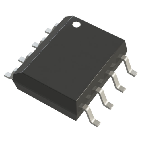
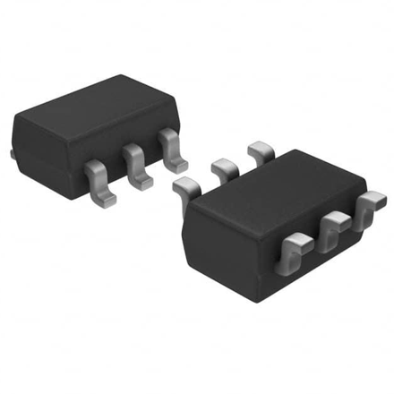
Housed in a small SOIC8 surface-mount package, the chip is easy to integrate into circuits. It features Pb-free construction, with 100% matte tin plating compatible with lead-free PCB assembly processes. The device is factory-calibrated for accuracy before shipment, ensuring reliable performance in applications such as motor control, load detection, switched-mode power supplies, and overcurrent protection.
Alternatives and substitute to the ACS712 include the ACS725 and ACS70331 models.
ACS712 Hall Effect Sensor Working Principle
The current sensor operates based on the Hall effect, a phenomenon where a magnetic field generates a voltage perpendicular to the direction of current flow. Inside the ACS712, place a linear Hall sensor circuit near a copper conduction path through which current flows. As current passes through this copper path, it creates a magnetic field that is proportional to the current.
The Hall element senses this magnetic field and generates a voltage signal that is directly proportional to the current. This voltage signal is then processed by internal amplification and signal conditioning circuits, including filtering and chopping, to enhance accuracy and reduce noise. The processed signal is output on the VOUT pin, which provides a voltage that corresponds to the magnitude of the current.
The ACS712 has a linear relationship between the output voltage and the current. The voltage output increases with positive current flow and decreases with negative current flow. The sensor chip can measure both DC and AC currents, and its output is ratiometric to the supply voltage, making it easy to read by a microcontroller.
The hall sensor chip widely use for non-invasive current measurement, offering high voltage isolation and enabling precise current monitoring in various applications such as motor control, load detection, and overcurrent protection.
ACS712 Current Sensor Pinout :
The circuit features 8 pins-SOP, and understanding their function is necessary for proper implementation:
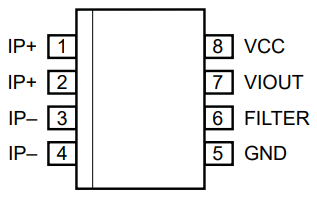
Pin | Name | Description |
1 & 2 | IP+ | Terminals for current being sensed (internally fused) |
3 & 4 | IP- | Terminals for current being sensed (internally fused) |
5 | GND | Ground pin for the signal path |
6 | FILTER | Pin for external capacitor to filter noise |
7 | VOUT | Output voltage signal, proportional to the current |
8 | VCC | Power supply terminal (typically 5V) |
Important Notes:
The FILTER pin allows you to attach an external capacitor to set the bandwidth and filter out high-frequency noise, ensuring cleaner readings.
The VOUT pin provides an analog voltage output, which corresponds to the current flowing through the conductor.
Current Sensor ACS712 Features
The ACS712 current sensor is a highly versatile and reliable solution for measuring both AC and DC currents. It comes in multiple models, including ACS712-05B, 5A, ACS712-10A, ACS712-20A, ACS712-30A, ACS712-50A, ACS712-100A, as well as versions for 3.3V systems and 220V AC applications.
One of the ACS712’s standout features is its low-noise analog signal path, which ensures precise measurements even in noisy environments. The device’s bandwidth is adjustable via the FILTER pin, enabling customization of noise filtering and band-width settings. It responds to step input currents with a 5 μs output rise time and has a bandwidth of up to 50 kHz, making it suitable for fast dynamic measurements.
The sensor has an internal conductor resistance of just 1.2 mΩ, ensuring minimal power loss during current sensing. Design to handle high-voltage isolation, with a minimum of 2.1 kVRMS-isolation between the current-carrying (pins 1-4) and the signal output terminals (pins 5-8). This makes it ideal for applications requiring electrical isolation.
The output-sensitivity of the ACS712 ranges from 66 to 185 mV/A, depending on the model, providing a linear and ratiometric output that is proportional to the measured current. The sensor operates with a single 5V supply and is factory-calibrated for accuracy, with a total output error of 1.5% at 25°C and 4% from -40°C to 85°C.
Additional features include an extremely stable output offset voltage, nearly zero magnetic hysteresis, and a small footprint in an easy-to-integrate SOIC8 package. These qualities make the ACS712 an excellent choice for applications such as motor control, load detection, switched-mode power supplies, and overcurrent protection.
ACS712 Current Sensor Datasheet PDF
ACS712 Chip Applications
The current sensor widely use across various applications as its ability to measure both AC and DC currents with high accuracy. ACS712’s linear analog output makes it ideal for systems that require precise current measurements.
Use in motor control applications to monitor the current drawn by motors, ensuring that the current remains within safe limits. This helps prevent damage to motors and connected equipment.
Load Detection: Ideal for monitoring load currents in systems to ensure that electrical circuits do not become overloaded. It plays a role in protecting sensitive devices from excessive currents.
In switched-mode power supplies (SMPS), the ACS712 employ to monitor the input and output currents, enabling precise regulation of power and improving the efficiency of the power conversion process.
Use in over-current protection circuits to detect excessive current and trigger system shutdowns, protecting against potential damage to components or electrical fires.
ACS712 IC Industrial Application
The circuit is indispensable in various industrial applications, where reliable current sensing is necessary for safety and efficiency. ACS712’s high voltage isolation and accurate current measurement make it well-suited for heavy-duty environments.
Energy Management: The ACS712 provides real-time current data, helping industries optimize energy usage and reduce waste.
Fault Protection: In industrial machinery, use for overcurrent protection, detecting faults and preventing damage to equipment or wiring. It can trigger protective relays to cut off power when necessary, ensuring system reliability and safety.
Indirect Current Sensing with the ACS712 IC
Indirect-current sensing with the ACS712 refers to measuring the current flowing through a conductor without directly placing the sensor in the current path. Instead, the sensor detects the magnetic field generated by the current, allowing you to measure the current indirectly, without interrupting the flow of electricity or making direct contact with the conductor.
This approach is particularly useful in systems where it’s impractical or unsafe to break the circuit for direct current measurement. For example, in a motor or high-voltage power system, can place the ACS712 around the current-carrying wire or conductor to sense the magnetic field generated by the current without physically touching the wire. This method is both non-invasive and safe, especially in high-voltage applications where requiring electrical isolation.
How It Works:
Current Flow: When current flows through a conductor, it generates a magnetic field around the conductor.
The ACS712 senses this magnetic field via the Hall-effect sensor integrated inside the chip.
Analog Output: The Hall-effect sensor then converts the magnetic field strength into an analog voltage output, which is proportional to the current flowing through the conductor.
By placing the ACS712 around the conductor, it provides a linear, proportional voltage output based on the current flowing, allowing the current to be measured indirectly and safely. This method is useful in applications such as motor monitoring, load detection, and overcurrent protection, where direct connection to high-current paths would be impractical or risky.
Using ACS712 Current Sensor with Arduino
The ACS712 current sensor can integrate easily with an Arduino to measure both AC and DC currents in your projects. Its analog output makes it compatible with the analog-input pins of Arduino boards, providing real-time current data that can process in your Arduino-code.
Pinout and Wiring Process
Here’s how to connect the ACS712 to your Arduino:
1. VCC (Pin 8): Connect this pin to the 5V pin on the Arduino to power the ACS712 sensor.
2. GND (Pin 5): Connect the ground pin to the GND pin on the Arduino.
3. VOUT (Pin 7): This is the analog output pin. Connect this pin to one of the analog input pins on the Arduino (e.g., A0). The sensor will output a voltage proportional to the current, which Arduino will read.
4. IP+ (Pin 1 and 2): Connect these pins to the current-carrying conductor where you want to measure the current. This is where the current flows through the sensor.
5. IP- (Pin 3 and 4): These are the opposite ends of the current path. Take the current measurement between these two pins.
Benefits of Using ACS712 with Arduino
1. Simple Integration: The circuit provides an analog voltage output that can directly read by the Arduino’s analog input pin, making it easy to integrate without needing complex circuits.
2. Real-Time Measurement: The ACS712 continuously provides real-time current readings, which is ideal for applications such as motor control, overcurrent protection, and power monitoring.
3. Cost-Effective: The hall effect sensor is affordable and readily available, making it a cost-effective solution for DIY projects and prototyping with Arduino.
4. Versatility: It can measure both AC and DC currents, making it versatile for a wide range of projects, from simple circuits to more complex systems.
5. Safety: The high voltage isolation (2.1 kVRMS) ensures safe operation, particularly when measuring currents in high-voltage systems, reducing the risk of electrical shock.
6. Easy Calibration: The sensor is factory-calibrated, which means you can get accurate readings right out of the box without needing extensive calibration.
ACS712 Hardware Assembly
The current sensor can integrate easily into your circuit for accurate current measurement. Here’s how to assemble the hardware:
1. Powering the Sensor:
VCC (Pin 8): Connect to the 5V pin of your microcontroller (e.g., Arduino).
GND (Pin 5): Connect to the ground of your system.
2. Current Path:
IP+ (Pins 1 & 2): Connect to the positive side of the current path you want to measure (e.g., motor, power supply).
IP- (Pins 3 & 4): Connect to the negative side of the current path.
3. Analog Output:
VOUT (Pin 7): Connect this pin to an analog input on your microcontroller (e.g., A0 on Arduino) to read the current measurement as a voltage.
4. Noise Filtering (Optional):
FILTER (Pin 6): For noise reduction, connect an external capacitor (typically 0.1 µF to 10 µF) to this pin.
Example Setup
For an Arduino setup, wire VOUT to A0, VCC to 5V, and GND to ground. The ACS712 will output an analog voltage that corresponds to the current flowing through the conductor, allowing you to calculate current using your Arduino.
This simple setup allows real-time current monitoring for applications like motor control, load detection, and overcurrent protection.
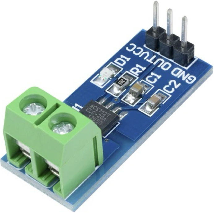
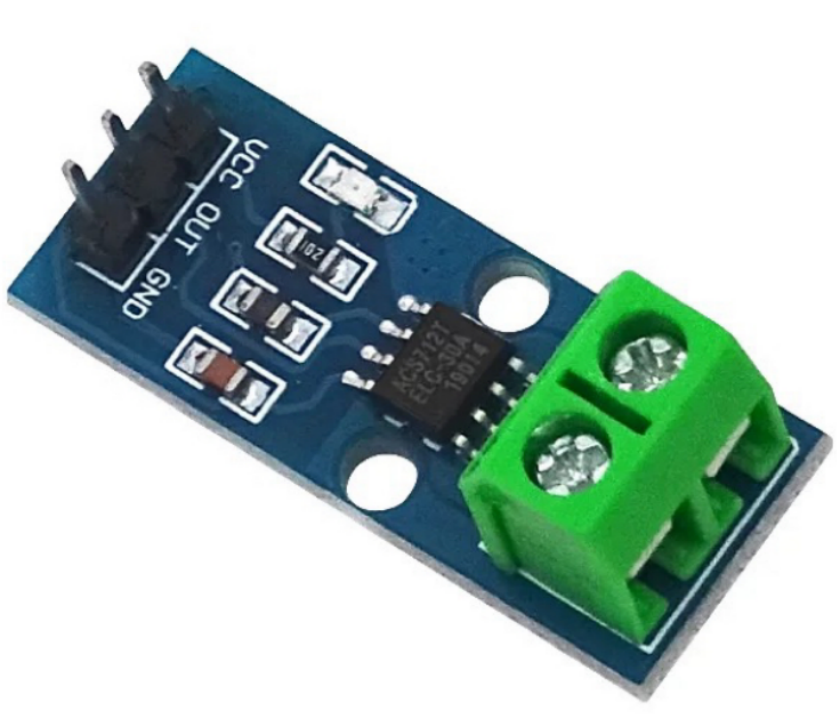
ACS712 5A Hall Effect Current Sensor Module Board
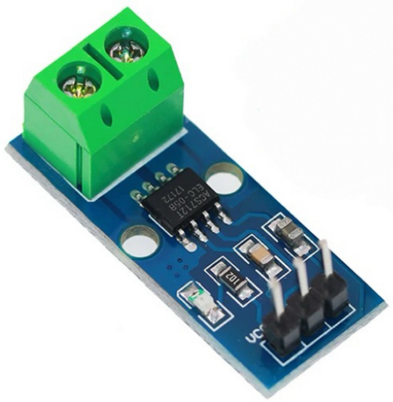
The ACS712 5A Hall Effect Current Sensor Module is a powerful and reliable solution for current measurement in a wide range of applications. It utilizes the ACS712 chip, available in different current sensing ranges, such as ±5A, ±20A, and ±30A, allowing it to measure both AC and DC currents with high accuracy.
Working Principle
The core of the ACS712 module design based on the Hall-effect, where combine a linear Hall sensor circuit with a copper foil conductor placed near the chip’s surface. When current flows through the copper foil, it generates a magnetic field that detect by the Hall element. This magnetic field induces a linear voltage signal that is proportional to the current. After amplify and process the signal through internal filtering, chopping, and correction circuits, a voltage signal is output.
The output signal is available at Pin 7 of the ACS712 chip and directly reflects the magnitude of the current flowing through the copper conductor. This analog signal varies linearly with the current and can read by a microcontroller (like Arduino) through an analog input pin.
Module Features
Current Measurement: Measures currents in ±5A, ±20A, or ±30A ranges, making it suitable for a variety of applications.
5V Power Supply: The module operates with a 5V power supply, commonly use in Arduino or other microcontroller systems.
Includes an on-board power indicator LED to indicate when the module is powered and operational.
Applications
This module widely use in applications requiring precise current measurement, including motor control, power monitoring, load detection, and overcurrent protection. The good linear relationship between input and output ensures accurate current sensing within the specified ranges.
By using this module, you can integrate current measurement capabilities into your projects with minimal setup and achieve reliable and accurate readings for both AC and DC systems.
Frequently Asked Questions [FAQ]
What is ACS712 price?
The ACS712 current sensor typically price between US$0.30 to US$2.00, depending on the specific model (e.g., ±5A, ±20A, or ±30A) and the supplier. Prices vary based on factors such as quantity, region, and whether the sensor is part of a module board or sold as a single chip. Bulk purchases offer discounted rates. It's widely available from online electronics suppliers such as Amazon, eBay, or Orwintech Electronics, making it an affordable option for hobbyists and professionals alike.
How to use ACS712 current sensor?
To use this chip, connect the VCC pin to 5V, the GND pin to the ground, and the VOUT pin to an analog input pin on your microcontroller (e.g., A0 on Arduino). The IP+ and IP- pins are for the current path you want to measure, placed in series with the current-carrying conductor. Once connected, you can read the output voltage from VOUT, which is proportional to the current. The sensor is ideal for both AC and DC current measurements.
How accurate is ACS712?
The ACS712 offers an accuracy of ±1.5% at 25°C. The total output error increases to ±4% across the operating temperature range of -40°C to 85°C. Its analog output voltage is ratiometric to the supply voltage, with a typical output sensitivity of 185 mV/A for the ±5A version. Although it's reasonably accurate for many applications, higher-precision current sensing require additional calibration or more advanced sensors. However, for general-purpose measurements, the ACS712 provides a reliable solution at an affordable cost.
What are the advantages of the ACS712 sensor?
There are several key advantages: ACS712’s cost-effective, easy to integrate with microcontrollers like Arduino, and provides linear output proportional to current, making it simple to interpret. It supports both AC and DC current measurements with high voltage isolation (2.1 kVRMS). The small footprint and 5V operation make it ideal for compact and portable projects. It also has a low internal resistance (1.2 mΩ), minimizing power loss. Additionally, the sensor is factory-calibrated, requiring minimal setup for accurate current sensing.
Is ACS712 analog or digital?
The ACS712 is an analog current sensor. It provides a continuous analog voltage output that is proportional to the current flowing through the sensor's copper conduction path. Can read this analog output by the input pin of a microcontroller (e.g., Arduino), and is typically ratiometric to the supply voltage. As the current flowing through the conductor increases, the output voltage increases linearly. Conversely, as the current decreases, the output voltage drops proportionally.
Can ACS712 measure AC current?
Yes, the ACS712 can measure both AC and DC currents. For AC current measurement, the sensor detects the magnetic field generated by the alternating current flowing through the conductor. The output voltage fluctuates in sync with the current's waveform. Since the ACS712 produces an analog output, you can measure the average current (for DC) or calculate the RMS current (for AC) using appropriate algorithms or a microcontroller’s built-in functions.
Is ACS712 A Hall effect sensor?
Yes, the ACS712 is a Hall effect sensor. It utilizes a linear Hall sensor circuit to detect the magnetic field generated by current flowing through a conductor. The sensor's copper conduction path generates this magnetic field, which is then sensed by the Hall element. Convert the induced magnetic field into a proportional voltage output, which varies linearly with the amount of current flowing through the conductor. The Hall effect allows for non-invasive current measurement, providing electrical isolation between the sensor and the current path.
How do I reduce noise in ACS712?
To reduce noise in the ACS712, you can add an external capacitor to the FILTER pin (Pin 6) to filter high-frequency noise. A typical capacitor value ranges from 0.1µF to 10µF, depending on your application and the level of noise present. Additionally, ensuring proper grounding and shielding in the circuit can minimize noise interference. Using stable, clean power for the ACS712 and placing the sensor away from high-frequency sources (such as motors or switching power supplies) also helps improve measurement accuracy.
Conclusion
The ACS712 Current Sensor is a reliable solution for current measurement in various applications, from motor control to load detection. With its Hall-effect technology, low internal resistance, and high voltage isolation, the circuit provides an economical and precise way to monitor current in both AC and DC circuits. Whether you're a DIY enthusiast or working on industrial systems, the ACS712 is a fantastic choice for your current sensing needs.
Read More:
1. Guide To The XL6009 Boost Converter
HOT NEWS
Understanding A 0603 Resistor
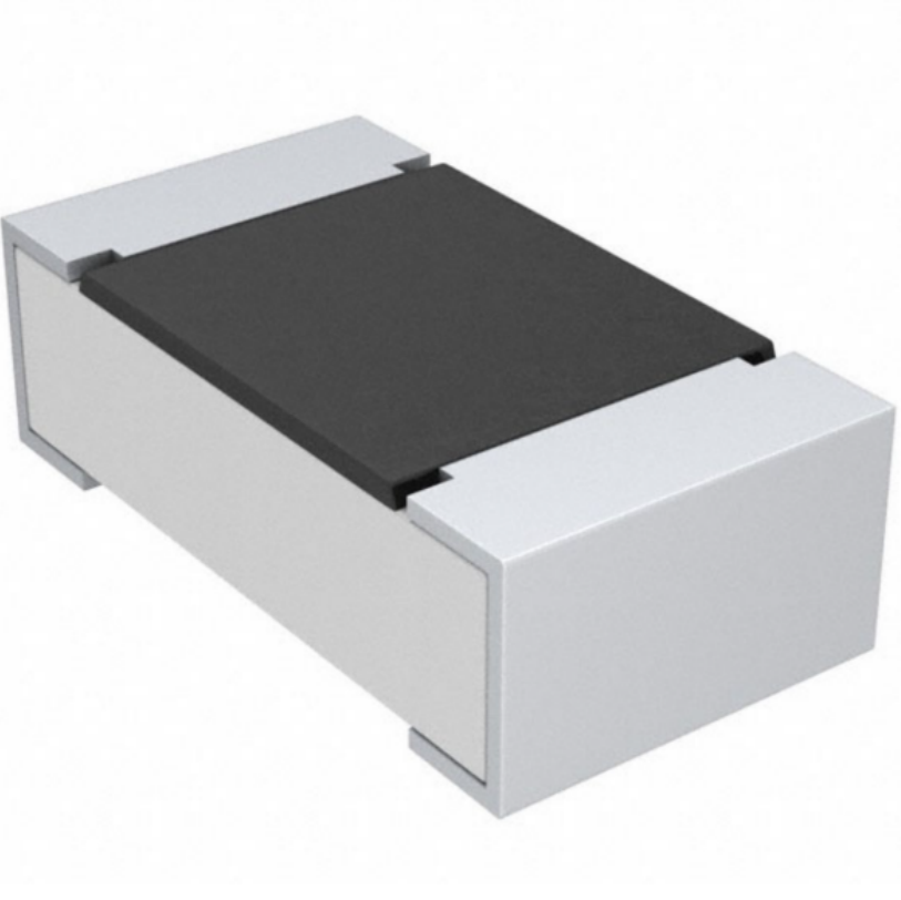
0603 resistor,dimensions,marking code, values
2025-05-29
The 0402 Resistor: A Comprehensive Guide
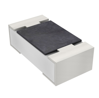
0402 Resistor
2025-05-06
LR41 Battery Guide: Specifications, Equivalents, and Uses
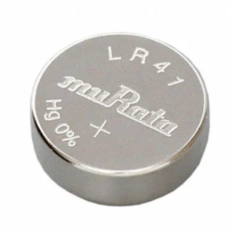
LR41 Battery Specifications, Equivalents, and Uses
2025-12-14
MT3608 Boost Converter - An In-Depth Guide
MT3608 Boost Converter
2025-09-04
What Is A 1206 Resistor?
1206 resistor dimensions,footprint,value
2025-06-05
TP4056 Charging Module Pinout, Working, and Applications
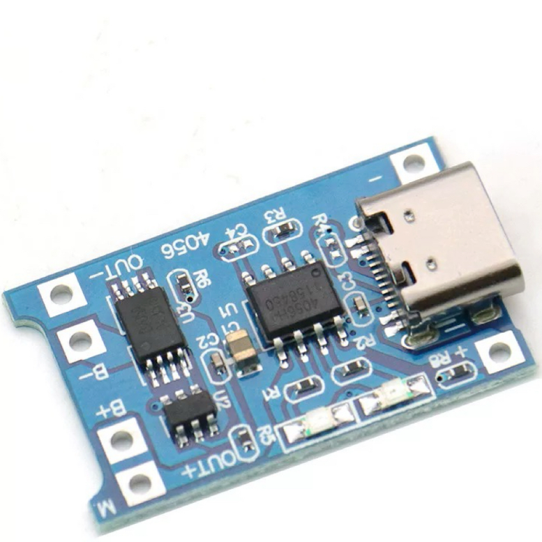
TP4056 Charging Module Pinout, Working, and Applications
2026-01-23
Everything You Need To Know About ARE1309 Relay
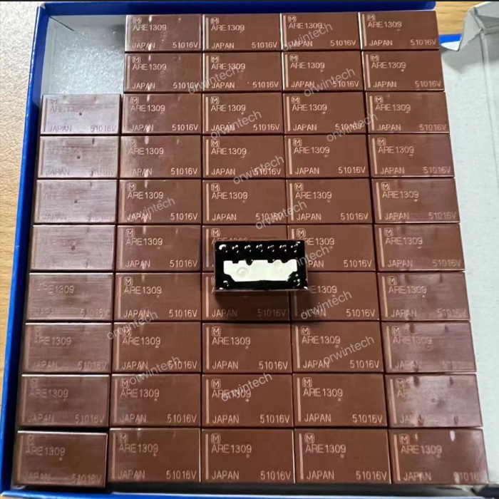
2025-04-23
Complete Guide to the 220 Ohm Resistor
220 Ohm Resistor
2025-07-28
120 Ohm Resistor- Specifications, Applications, and Features
2025-05-12
Guide To The AMS1117 Voltage Regulator
AMS1117 Voltage Regulator Circuit
2025-08-17