


 BOM
BOM Cart
Cart Product Catalog
The DS1302 Real-Time Clock (RTC) IC from Maxim Integrated (formerly Dallas Semiconductor) is one of the most popular and reliable options for embedded systems requiring precise time and date tracking. This low-power chip design for ease of use, with a simple interface, compact size, and robust features. In the world of embedded systems, accurate timekeeping is often necessary for a wide range of applications. Whether it's for logging data, creating clocks, or synchronizing tasks, time is a key factor. In this comprehensive guide, we’ll dive deep into the details of the DS1302, including its features, applications, specifications, and design insights.
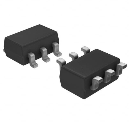
Package Types of DS1302 SMD DIP and Pinout
Applications of DS1302 Real Time Clock
Frequently Asked Questions [FAQ]
What is the DS1302 Chip?
A real time clock and calendar IC that contains a real-time clock/calendar and 31 bytes of static RAM for data storage. Design to communicate with a microcontroller via a simple serial interface, making it a versatile choice for various microcontroller-based applications, from hobbyist projects to industrial use.
Core Functions:
Timekeeping: The chip keeps track of seconds, minutes, hours, day of the week, date of the month, month, and year, with automatic leap year adjustment. This means the DS1302 accounts for months with fewer than 31 days (February, April, June, etc.) and adjusts the date accordingly.
Dual Power Pins: One of the most notable features of the IC is its dual power pin design. It has a primary supply voltage (VCC) and a backup supply pin (VBAT), ensuring that the timekeeping functions continue uninterrupted even if the primary power disconnect. When the primary power is lost, the chip switches to battery power and continues running, retaining the clock data.
Low Power Consumption: An energy-efficient chip. In standby mode, it consumes less than 1µW of power, making it an excellent choice for battery-operated devices.
Time Format: The chip supports both 12-hour and 24-hour time formats. When in 12-hour mode, it includes an AM/PM indicator, which is require for certain applications, such as clocks and alarms.
Communication: The DS1302 communicates with microcontrollers via a simple 3-wire interface: CE (Chip Enable), SCLK (Serial Clock), and I/O (Data Line). This minimizes the number of pins required on the microcontroller, making it ideal for constrained spaces and low-pin-count MCUs.
Data Transfer in two modes: Single-Byte Mode, transfer each byte of data individually. Burst Mode, transfer up to 31 bytes at once, making the process faster when transferring larger data sets.
Features of the DS1302 IC
The RTC IC chip offers a range of features design to provide reliable and efficient timekeeping for embedded systems and low-power applications.
It fully manages all timekeeping functions, tracking seconds, minutes, hours, day of the week, date of the month, month, and year, with leap-year compensation valid up to the year 2100. The chip also includes 31 bytes of battery-backed static RAM, which can use for storing user data or other relevant information that needs to persist when the device power off.
The DS1302 interfaces easily with most microcontrollers, thanks to its simple 3-wire serial interface, which requires just CE (chip enable), I/O (data line), and SCLK (serial clock) pins. TTL-compatible, making it suitable for a wide range of systems that operate at 5V logic levels.
Can transfer data from or to the chip in either single-byte mode or burst mode (multiple bytes), allowing for flexible communication depending on the needs of the application.
The chip design for low power operation, consuming less than 300nA at 2.0V. It operates across a wide voltage range of 2.0V to 5.5V, extending battery backup run time, making it an excellent choice for battery-powered devices.
With its 8-PDIP and 8-SOIC packages, the chip minimizes space requirements for compact designs. Additionally, the clock chip offers an optional industrial temperature range of -40°C to +85°C, ensuring reliability in harsh environmental conditions.
The chip is Underwriters Laboratories (UL) recognized, signifying its compliance with safety standards for a wide variety of applications.
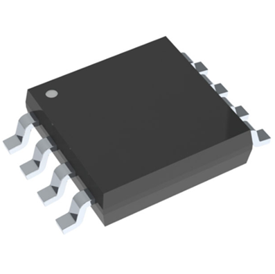
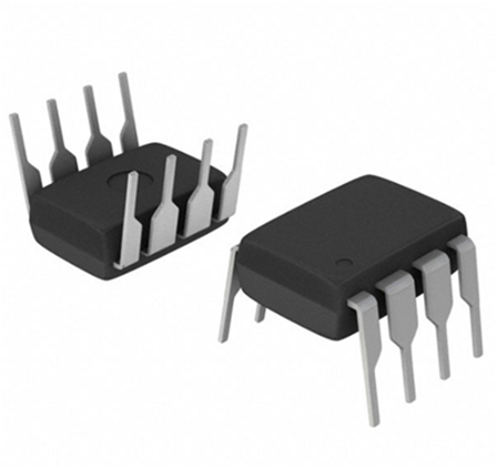
Package Types of DS1302 SMD DIP and Pinout
Available in a range of packing types, allowing to use it in various designs, from DIY electronics projects to industrial applications.
DS1302 SMD: Available in 8-SOIC and 16-SOIC configurations with various pin spacing and size options, including 150 mils and 208 mils versions. The lead-free and RoHS-compliant variants mark with a +.
DS1302 DIP: Available in 8-PDIP with a 300 mils pin spacing, offering a traditional through-hole mounting option for applications where need a larger package.
Part Number | Package Type | Pin Count |
DS1302S+ | 8-SOIC (208 mils) | 8 |
DS1302SN+ | 8-SOIC (208 mils) | 8 |
DS1302Z+ | 8-SOIC (150 mils) | 8 |
DS1302ZN+ | 8-SOIC (150 mils) | 8 |
DS1302SN-16 | 16-SOIC | 16 |
DS1302S-16 | 16-SOIC | 16 |
DS1302+ | 8-PDIP (300 mils) | 8 |
DS1302N+ | 8-PDIP (300 mils) | 8 |
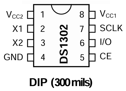
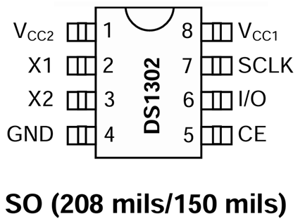
Pin Number | Pin Name | Function |
1 | VCC2 | Primary power-supply pin in dual-supply configuration. VCC1 maintains time and date when VCC2 is absent. The chip operates from the higher of VCC1 or VCC2. |
2 | X1 | Connection for a 32.768kHz quartz crystal. Internal oscillator works with a crystal having 6pF load capacitance. Can also drive by an external oscillator. |
3 | X2 | Connection for a 32.768kHz quartz crystal. Similar to X1, it supports 6pF load capacitance. In case of external oscillator, X2 is left unconnected. |
4 | GND | Ground pin. |
5 | CE | Chip Enable pin. Must be asserted high during read or write. Has an internal 40kΩ pull-down resistor. Previously referred to as RST. Function remains unchanged. |
6 | I/O | Bidirectional data pin for the 3-wire interface. Use for reading/writing data. Has an internal 40kΩ pull-down resistor. |
7 | SCLK | Serial clock input to synchronize data movement on the 3-wire interface. Has an internal 40kΩ pull-down resistor. |
8 | VCC1 | Low-power operation pin in single-supply systems and for battery backup. UL-recognized to prevent reverse charging when used with a lithium battery. |
Applications of DS1302 Real Time Clock
The RTC IC widely use in various applications where precise time and date tracking are necessary. Some of the key applications include:
In embedded systems, use in microcontroller projects where time and date is important, such as in microcontroller-based clocks, alarms, and time-sensitive data logging. Also in home automation systems to schedule events such as turning on/off lights or controlling appliances based on time.
In digital clocks and watches, use to maintain accurate timekeeping in devices such as wall clocks, wristwatches, and alarm clocks. Can trigger alarms based on set times.
In data logging systems, use for applications that require the logging of time-stamped data, such as temperature data loggers or environmental monitoring systems that track conditions such as humidity, pressure, or light levels.
In industrial systems, can keep track of time in factory machines or systems, logging work shifts or operational hours. Also use in equipment maintenance scheduling or tracking the operational time of machinery.
The RTC chip is valuable in power failure recovery scenarios. Commonly use to back up time during power failures in critical applications. It continues to run with a battery (through VCC1) and restores time once the system power back up.
In smart appliances, use in devices such as smart refrigerators, ovens, or programmable microwaves to enable time-dependent functions, such as defrost cycles or temperature control.
In security systems, can use for time-stamped surveillance events such as door openings or motion detection, as well as for access control systems to track when access events occur in buildings.
The clock chips can also use in time and date display systems such ticketing systems, where it helps print time-stamped tickets in parking lots or transportation, or in calendar and event systems that require time and date functionality.
In toys and games, the IC can use in devices to keep track of time, set timers for activities, or create challenges based on time.
These are some of the common applications of the DS1302. Its low power consumption and small size make it suitable for a wide range of time-sensitive applications.
DS1302 Datasheet & Design
Here’s a detailed breakdown of the circuit Design:
DS1302 Real Time Clock Module ( with/without CR2032 battery )
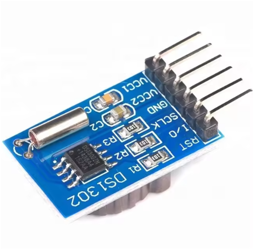
The DS1302 module commonly use in embedded systems, Arduino projects, and IoT devices. The module usually includes: The DS1302 chip, a 32.768kHz quartz crystal for accurate timekeeping, battery holder for a backup power source, ensuring the time maintain even when the main power supply disconnect. Pull-up resistors (typically 10kΩ or 4.7kΩ) for the CE, SCLK, and I/O pins.
Features of the Module With a CR2032 Battery:
Battery Backup: The CR2032 coin cell provides a low-power backup to keep the RTC circuit running during power outages.
Low Power Consumption: The circuit consumes little power (less than 1 µA) during battery backup, making the CR2032 battery last for years.
Seamless Power Switching: The chip automatically switches between the main supply (VCC2) and backup battery (VCC1) based on which one is available. If VCC2 (primary power) is available, it will power the circuit, and if VCC2 is absent, it switches to the CR2032 battery.
Time Retention: When powered by the battery, the chip will continue tracking seconds, minutes, hours, and even the day, month, and year, including leap year handling.
Applications with Battery:
Portable and Battery-Operated Devices: Ideal for systems where the device might not be continuously powered (e.g., portable clocks, weather stations, and remote sensors).
Data Logging Systems: Useful in applications where time-stamped data is necessary, such as logging temperature, humidity, or other sensor data.
IoT Devices: Many Internet of Things(IoT) devices use the IC with a battery backup to ensure accurate timestamps in the absence of continuous power.
Arduino RTC DS1302 Real Time Clock Example
To interface the chip with Arduino, you need to wire the module to your Arduino board using the 3-wire interface (CE, I/O, and SCLK). Here's a simple example setup:
Wiring: VCC (chip) to 5V (Arduino). GND (chip) to GND (Arduino). CE (chip) to Digital Pin 3 (Arduino). SCLK (chip) to Digital Pin 4 (Arduino). I/O (chip) to Digital Pin 5 (Arduino).
Code Example:
#include <Wire.h>
#include <DS1302.h>
DS1302 rtc(3, 4, 5); // CE, SCLK, I/O pins
void setup() {
Serial.begin(9600);
rtc.begin();
rtc.setTime(12, 0, 0); // Set initial time (12:00:00)
}
void loop() {
int hour = rtc.getHour();
int minute = rtc.getMinute();
int second = rtc.getSecond();
Serial.print(hour);
Serial.print(":");
Serial.print(minute);
Serial.print(":");
Serial.println(second);
delay(1000);
}
This code initializes the DS1302, sets an initial time of 12:00:00, and continuously displays the current time on the Serial Monitor.
ESP8266 DS1302 (with ESP32/ESP8266)
The chip is compatible with ESP8266 and ESP32 boards, which often use in Wi-Fi-based applications. The pinout and wiring are similar to Arduino but keep in mind that the ESP boards use 3.3V logic, so ensure proper voltage levels for the DS1302, which operates at both 3.3V and 5V.
Wiring (ESP8266 Example):
VCC (DS1302) to 3.3V (ESP8266).
GND (DS1302) to GND (ESP8266).
CE (DS1302) to GPIO Pin 2 (ESP8266).
SCLK (DS1302) to GPIO Pin 0 (ESP8266).
I/O (DS1302) to GPIO Pin 4 (ESP8266).
Code Example for ESP8266:
#include <Wire.h>
#include <DS1302.h>
DS1302 rtc(D2, D1, D3); // CE, SCLK, I/O pins
void setup() {
Serial.begin(115200);
rtc.begin();
rtc.setTime(12, 0, 0); // Set initial time
}
void loop() {
int hour = rtc.getHour();
int minute = rtc.getMinute();
int second = rtc.getSecond();
Serial.print(hour);
Serial.print(":");
Serial.print(minute);
Serial.print(":");
Serial.println(second);
delay(1000);
}
This example works similarly to the Arduino example but on an ESP8266 or ESP32, showing how to read and print the current time.
The DS1302 Real-Time Clock works seamlessly with platforms like Arduino, ESP8266, and ESP32 for both simple and advanced time-dependent tasks. The module's low power consumption, ease of use, and backup battery make it suitable for a wide range of applications.
Frequently Asked Questions [FAQ]
1. What is the function of DS1302?
A low-power real-time clock (RTC) that tracks time and date information, including seconds, minutes, hours, day of the week, date, month, and year, with leap year compensation. It communicates via a 3-wire serial interface (clock, data, and chip enable), making it easy to integrate into microcontroller projects. The device can function on a primary power supply or a backup battery when the main power is lost, ensuring continuous timekeeping. It also includes 31 bytes of user-accessible RAM for temporary storage of data.
2. What is the difference between DS1302 and DS1307?
The main difference between the 2 chips lies in their communication protocol and power consumption. The DS1302 uses a simple serial interface (three-wire SPI), while the DS1307 uses I²C communication (two-wire). The DS1307 offers better accuracy with a ±2ppm specification, compared to the DS1302's ±5ppm. The DS1307 also supports a wider range of voltage (4.5V to 5.5V) and often consider more accurate and reliable for timekeeping. Additionally, the DS1307 features a higher-resolution crystal oscillator, offering better time stability than the DS1302. Both use a CR2032 battery for timekeeping during power loss.
3. What kind of battery is in the DS1302?
Typically use a CR2032 lithium coin cell battery for backup power. This battery ensures that the timekeeping function continues even when the primary power supply disconnect or fails. Design the backup battery to last several years and helps maintain accurate time and date information. The battery voltage typically ranges from 2.0V to 3.0V, and when remove the external power supply, the chip seamlessly switches to the backup battery to maintain accurate time. Commonly use the CR2032 because of its compact size, long life, and stable voltage output, which is ideal for low-power applications such as the DS1302.
4. What are the specs of DS1302?
The chip operates within a voltage range of 2.0V to 5.5V, making it suitable for a wide range of electronic projects. It consumes less than 100nA in battery mode, contributing to its low power consumption. The timekeeping accuracy of the circuit is approximately ±2 minutes per month at room temperature. It includes 31 bytes of static RAM for data storage and can operate in both 12-hour and 24-hour time formats. Typically use the RTC chip in battery-powered applications as its minimal power consumption and compact design.
The DS1302 is a powerful yet cost-effective solution for timekeeping in embedded systems, clocks, and data logging applications. With its low power consumption, easy interface, and dual power supply system, it's perfect for a wide range of uses, from hobby projects to industrial systems. Whether you're a beginner looking to build a clock or a professional designing a time-sensitive device, the RTC circuit offers reliable, accurate, and easy-to-implement timekeeping functionality.
Read More:
1. Guide To The AMS1117 Voltage Regulator
HOT NEWS
Understanding A 0603 Resistor
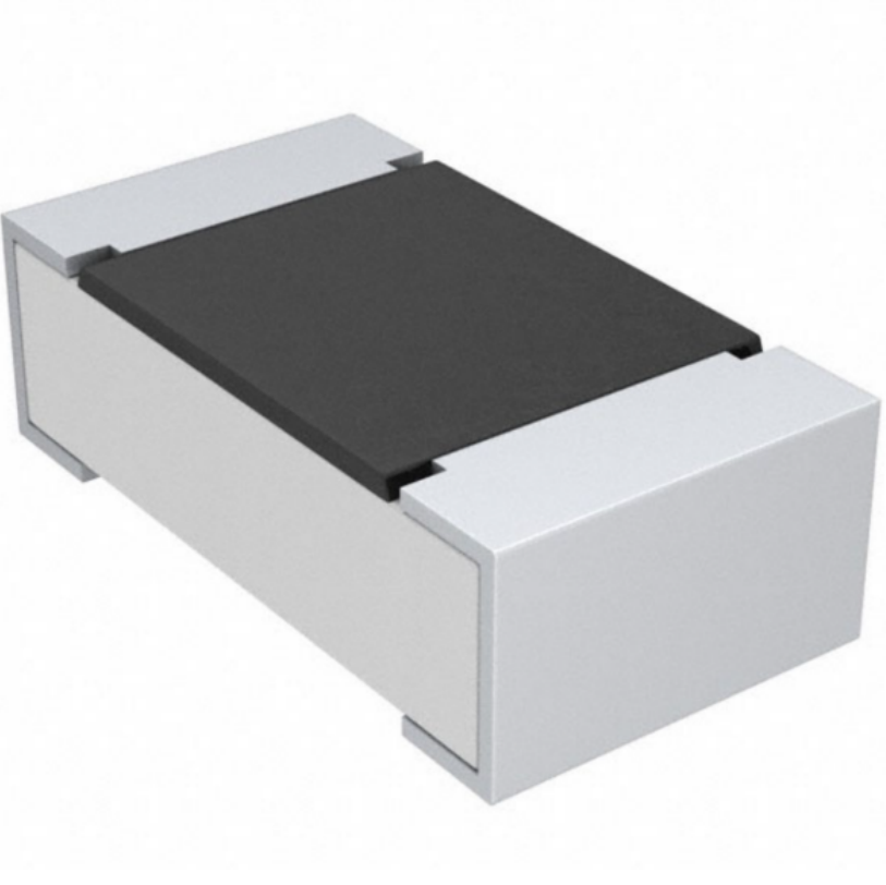
0603 resistor,dimensions,marking code, values
2025-05-29
The 0402 Resistor: A Comprehensive Guide
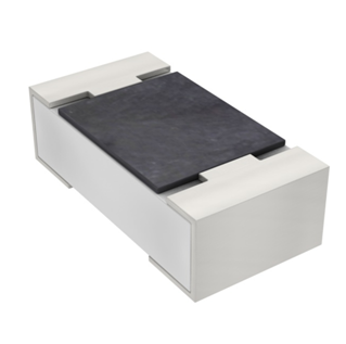
0402 Resistor
2025-05-06
LR41 Battery Guide: Specifications, Equivalents, and Uses
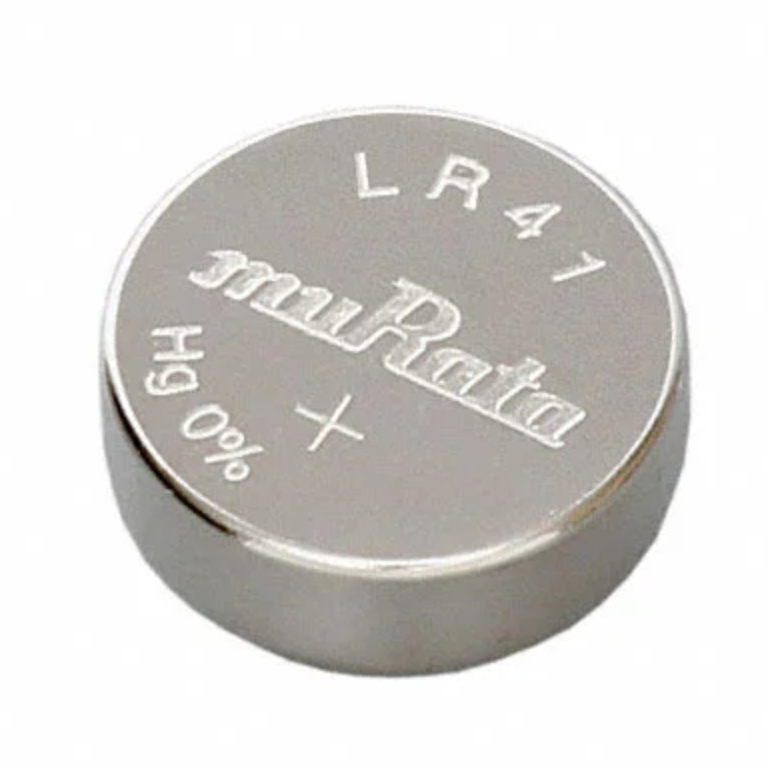
LR41 Battery Specifications, Equivalents, and Uses
2025-12-14
MT3608 Boost Converter - An In-Depth Guide
MT3608 Boost Converter
2025-09-04
What Is A 1206 Resistor?
1206 resistor dimensions,footprint,value
2025-06-05
TP4056 Charging Module Pinout, Working, and Applications
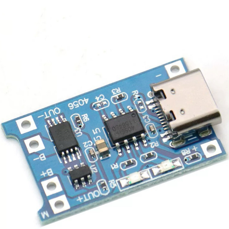
TP4056 Charging Module Pinout, Working, and Applications
2026-01-23
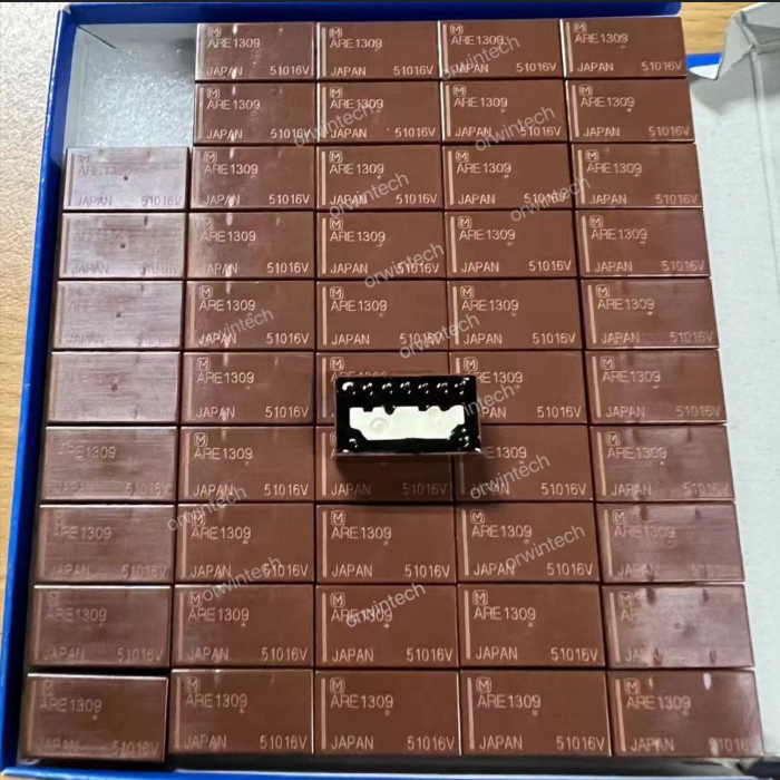
Everything You Need To Know About ARE1309 Relay
2025-04-23
Complete Guide to the 220 Ohm Resistor
220 Ohm Resistor
2025-07-28
120 Ohm Resistor- Specifications, Applications, and Features
2025-05-12
Guide To The AMS1117 Voltage Regulator
AMS1117 Voltage Regulator Circuit
2025-08-17