


 BOM
BOM Cart
Cart Product Catalog
The PC817 Optocoupler is one of the most commonly use components in modern electronic circuits. From simple hobby projects to complex industrial systems, optocouplers such as the PC817 provide isolation and noise suppression. In this guide, we will explore the various aspects of the PC817’s features, working principle, technical specifications, applications, and frequently asked questions.
1. What is a PC817 Optocoupler?
2. Working Principle of PC817 Circuit
3. Detailed Explanation of PC817 IC Optocoupler Characteristics and Technical Specifications
4. Pin Configuration of Opto Isolator PC817
5. Optoacoplador PC817 Alternative Equivalent Models
6. Circuit Design of PC817 Opto Isolator
7. How to Use PC817 Optocoupler Safely For a Long Time in the Circuit
8. Applications of Optoacoplador PC817
9. PC817 4 Channel Optocoupler Isolation Module Board
10. Frequently Asked Questions [FAQ] about Opto PC817
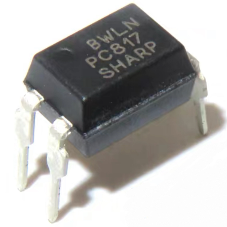
What is a PC817 Optocoupler?
A widely use electronic component design to provide electrical isolation between different parts of a circuit while allowing signal transmission. It belongs to a category of optoisolators, which use light to transmit electrical signals, thus isolating two sections of a circuit. The chip consists of an Infrared Emitting Diode (IRED) that optically couple to a phototransistor, making it ideal for signal isolation in various applications, from industrial systems to hobbyist projects.
The Manufacturer SHARP PC817’s series includes several variants that differ in the Current Transfer Ratio (CTR), which represents the efficiency with which transmit the input signal to the output.
Series No. | Current Transfer Ratio |
PC817A | Low (~50%) |
PC817B | Medium (~100%) |
PC817C | High (~200%) |
PC817D | High (~600%) |
The PC817x types isolator is typically a 1-channel opto coupler, meaning it designs to isolate a single input and output signal.
Working Principle of PC817 Circuit
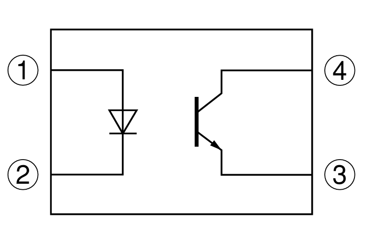
The Optocoupler operates based on the principle of optical isolation, which allows to transmit electrical signals between two isolated circuits. It consists of an Infrared Emitting Diode (IRED) on the input side and a phototransistor on the output side. The working principle step by step as follows:
LED (IRED) Emission (Input Side)
When apply a voltage to the input side of the PC817, a current flows through the LED(IRED). The LED is a diode that emits infrared light when current passes through it. The infrared light emitted by the LED is not visible to the human eye but can detect by the phototransistor on the output side. Typically use the current to activate the LED is around 5mA, depending on the variant of the circuit. The LED emits infrared light as the energy released when electrons move across the semiconductor material.
Optical Isolation (Light Transmission)
The infrared light generated by transmit the LED through an optical barrier that physically isolates the two circuits. The barrier typically make of transparent plastic or resin that allows the infrared light to pass through while preventing electrical contact between the input and output sides. This isolation ensures that high voltages on the input side do not affect or damage the output side of the circuit. The isolation voltage of the IC rates at 5.0kV RMS, meaning it can handle up to 5,000 volts of electrical isolation without failure.
Phototransistor Detection (Output Side)
The photo transistor on the output side detects the infrared light that passes through the optical barrier. When the phototransistor receives the light, it turns on and allows current to flow from the collector to the emitter. The photo-transistor essentially acts as a light-sensitive switch. The amount of current that flows through the photo transistor is proportional to the amount of light it receives from the LED. This allows the opto coupler to transfer the electrical signal in the form of light while maintaining electrical isolation.
Current Transfer Ratio (CTR)
The CTR is a key specification that defines how efficiently the optocoupler transfers current from the input (LED) to the output (phototransistor side). The CTR express as a percentage and calculate as the ratio of the output current to the input. For example, if the input current is 5mA and the output is 50mA, the CTR would be 100%. The PC817’s series have a CTR range from 50% to 600%, with different variants offering different levels of efficiency.
Output Side Circuitry (Load Control)
Once the photo-transistor conducts, it can control the current in the output circuit. This allows the optocoupler to interface with other components, such as microcontrollers, relays, or other low-power devices. The output of the phototransistor can drive the connected load or fed to the next stage of the circuit, depending on the application. The signal on the output side is a replica of the input signal, electrically isolate though the two circuits.
This system allows the PC817 to electrically isolate two circuits while still transmitting signals, making it ideal for protecting sensitive components from voltage spikes or surges.
Detailed Explanation of PC817 IC Optocoupler Characteristics and Technical Specifications
The Optocoupler widely use for signal isolation, offering key advantages such as electrical isolation between circuits, noise suppression, and protection from high-voltage surges. Below is a detailed explanation of the characteristics and specifications of the circuit to help you understand how it works in various electronic applications.
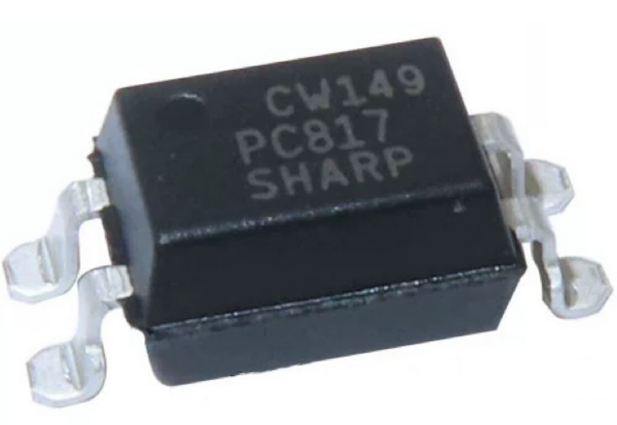
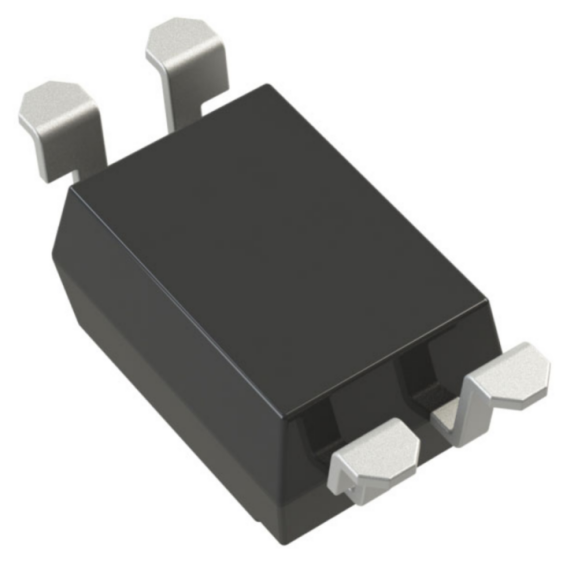
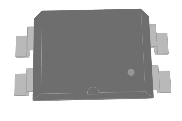
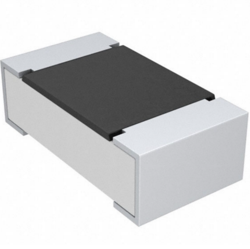
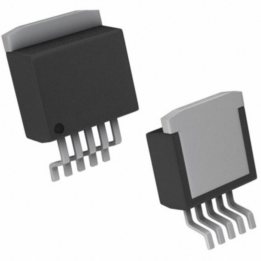
Two Package Types:
The PC817 is available in two primary packages , both types offer the same functionality, but the mounting style differs to accommodate different assembly techniques:
DIP Package: A traditional through-hole package with four pins and suite for manual assembly, prototyping, and designs where stable, through-hole connections are necessary.
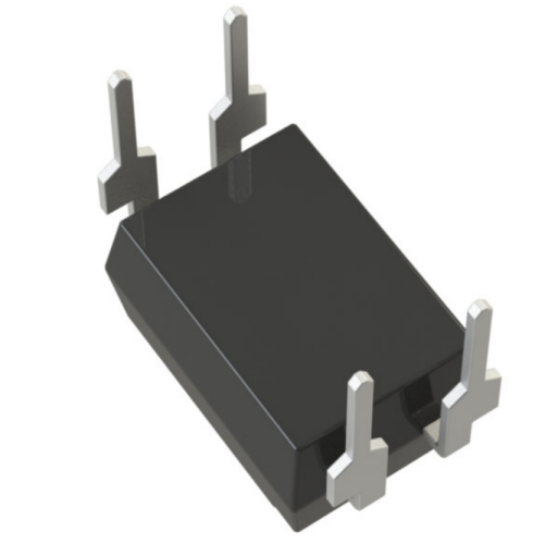
PC817 SMD: The Surface-Mounted Device (SMD) option design for automated assembly, is ideal for modern compact circuit designs where require space-saving and high-density PCB layouts.
Current Transfer Ratio (CTR)
The Current Transfer Ratio (CTR) defines the efficiency of the signal transfer from the LED side (input) to the phototransistor (output). The CTR express as the ratio of the output current to the input. The circuit offers different CTR ranges (MIN. 50% at IF= 5mA,VCE=5V).
A higher CTR indicates better signal transmission efficiency, with the PC817D offering the best performance for applications requiring higher signal fidelity.
Isolation Voltage
One of the key features is PC817’s electrical isolation between the input and output sides of the circuit. The isolation voltage rates at 5.0kV RMS, meaning it can handle a maximum of 5,000 volts between the input and output without allowing electrical breakdown. This high isolation ensures that sensitive components, such as microcontrollers or low-voltage circuits, protect from voltage spikes or surges in the system, making the PC817 ideal for safety-critical applications.
Collector-Emitter Voltage (VCEO)
The collector-emitter voltage (VCEO) rate at 80V, which refers to the maximum voltage that can apply across the phototransistor’s collector and emitter terminals without damaging the component. When the photo-transistor is in the "on" state, this voltage rating ensures that the component can safely conduct current without failure. The Isolator is suitable for low- to medium-voltage applications but may not be ideal for circuits requiring too high voltage isolation.
Forward Voltage (Vf)
The forward voltage (Vf) of the LED in the circuit typically ranges from 1.1V to 1.4V, depending on the input current. This is the voltage drop across the LED when it is conducting. When designing the circuit, must consider the forward voltage to ensure that use the correct current-limiting resistor. If the LED operates with a lower voltage than its forward voltage rating, it may not emit light effectively, affecting the performance of the optocoupler.
Operating Temperature Range
Operate within a temperature range of -30°C to +100°C, which makes it suitable for use in a variety of environmental conditions. The wide temperature range ensures that the optocoupler remains reliable and performs well in both low and high temperature environments. However, ensure that the operating temperature stays within this range to prevent overheating or performance degradation.
Packaging and Mounting
The PC817 comes in a double transfer mold package, making it durable and ideal for flow soldering processes. This ensures that the component can withstand the heat associated with automated soldering techniques, which is particularly important for mass production. The DIP package is suitable for traditional through-hole mounting, while the SMD version is more appropriate for automated surface-mount processes. Both packaging options design to be reliable and robust, ensuring long-term durability and performance.
Reliability and UL Recognition
UL recognized under File No. E64380, which indicates that it meets strict safety and quality standards for reliable operation. Means that the circuit has test and approve for use in various consumer and industrial applications where safety and performance are paramount.
Response Time (Switching Speed)
The isolator is not design for high-speed switching applications. Its turn-on and turn-off times are relatively slow compared to other optocouplers. As such, it is more suitable for low- to moderate-speed applications where not require high-frequency switching. For high-speed communication or fast switching applications, optocouplers with faster response times, such as the 6N137 or FOD3180, may be more appropriate.
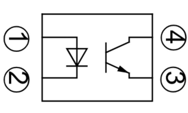
Pin Configuration of Opto Isolator PC817
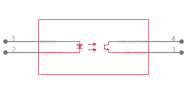
The Optocoupler has a 4-pin configuration that connects the input side (LED) and the output side (phototransistor).
Pin Layout and Functions
Pin 1: Anode (LED Side)
Pin 1 is the anode of the infrared emitting diode (IRED). This is the positive terminal where the current flows into the LED. A current-limiting resistor typically connect in series with this pin to control the current flowing through the LED and prevent damage to the diode.
Pin 2: Cathode (LED Side)
This is the negative terminal of the LED. When current flows from the anode to the cathode, the LED emits infrared light, which then transmit through the optical barrier to the phototransistor on the output side.
Pin 3: Emitter (Phototransistor Side)
The emitter is the region through which current exits the phototransistor. It connects to the ground or the negative side of the output circuit, depending on the design of the application. When the phototransistor detects the infrared light emitted by the LED, it begins to conduct, allowing current to flow through the collector.
Pin 4: Collector (Phototransistor Side)
The collector is the terminal where the current flows into the phototransistor when it turns on. The amount of current that flows through the collector depends on the amount of light received by the phototransistor from the LED. The collector pin typically connect to the output circuit where the signal is transmitting.
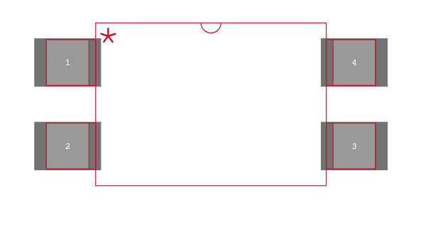
Precautions for Assembly and Wiring
When working with the Optocoupler, it’s necessary to consider the following assembly and wiring precautions:
Ensure place a current-limiting resistor in series with the anode (Pin 1) of the LED to prevent excessive current from damaging the LED.
Double-check the pinout of the optocoupler when inserting it into a breadboard or PCB to ensure that make the connections according to the correct pin configuration.
Make sure connect the LED side (Pins 1 and 2) with the proper polarity. Reversing the polarity of the LED side may prevent the optocoupler from functioning correctly.
Thermal Management: As with any semiconductor device, ensure proper heat dissipation, especially if the optocoupler will be operating in high-power conditions.
Correctly connecting the PC817 will ensure reliable operation and effective isolation between the input and output circuits.
Optoacoplador PC817 Alternative Equivalent Models
Features of PC817’s Alternatives Models:
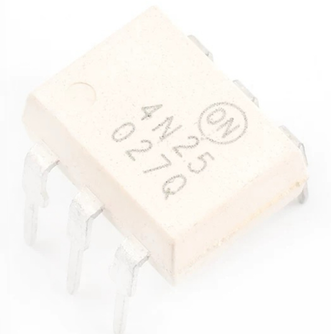
4N25
Low input current, High isolation voltage (5000 V), Compact package. Ideal for signal isolation and control systems.
4N35
High-speed switching, Enhanced performance in noisy environments, High isolation voltage (5000 V). Perfect for switching circuits, industrial control.
6N136
High-speed (15 Mbps), Logic-level output, Wide operating temperature range. Use for communication and data transmission.
6N137
Fast switching speed (20 Mbps), High isolation voltage (5000 V). Suitable for high-speed data isolation.
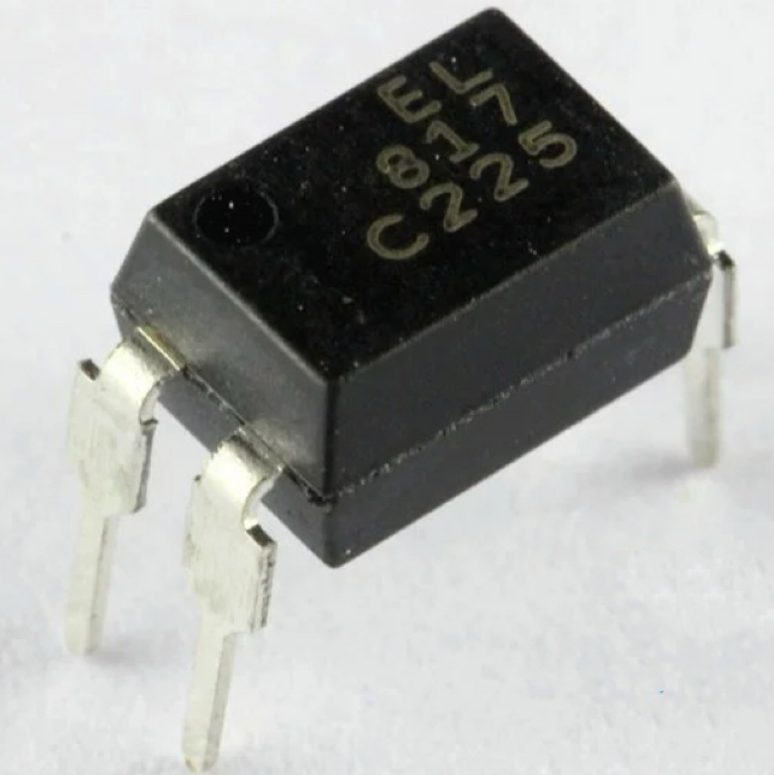
EL817
High isolation voltage, Phototransistor output, Low input current. Suitable for low-power control systems and logic isolators.
LTV-816
Low coupling capacitance, High isolation voltage (5000 V), Phototransistor output. Commonly use in industrial automation systems.
LTV-817
Improved speed and efficiency, High isolation voltage (5000 V).
Use for applications requiring high-speed switching and low power consumption.
ISP817X
Fast response time, High isolation voltage (5000 V), Low current consumption. Use for signal isolation in various communication systems.
MOC3021
High-speed switching, Triac driver output, Isolation voltage up to 5000 V. Design for use in AC control and switching applications.
MOC3041
Triac output for AC switching, High isolation voltage (2500 V). Often use in motor control and power switching circuits.
FOD3180
High-speed performance, Low input current, High isolation voltage (5000 V). Use in industrial applications requiring fast data transmission.
SFH615A
Phototransistor output, High isolation voltage (5000 V), Low current consumption. Primarily use in microcontroller and logic circuits for isolation.
PC816
Wide input voltage range, Phototransistor output. Common in consumer electronics for signal isolation.
PS2571-1
Fast switching, High isolation voltage, Low input current. Use in high-speed signal isolation in industrial and control systems.
PS2561-1
High isolation voltage (5000 V), High-speed switching, Phototransistor output. Use for applications requiring high-speed data isolation, such as in telecom systems.
Selection of Replacement Models
When choosing a replacement, consider the following factors:
Switching speed: Some models (such as 6N136 and 6N137) offer much faster switching speeds than the PC817, suitable for high-speed data applications.
Output type: Ensure that the replacement has the appropriate output type (e.g., phototransistor, photodiode) for your application.
Isolation voltage: The PC817 typically offers around 5KV isolation, so replacements such as 4N35, 6N137, and others with high isolation should consider if need.
Package type: Match the package type (through-hole vs. SMD) to your circuit's design. Some alternatives such as LTV-816 are available in both options.
Application requirements: Choose based on the need for control, signal isolation, and current handling capability. Models as MOC3021 and MOC3041 more suite for power control applications.
Model | Switching Speed | Application |
PC817
| Moderate | General-purpose isolation, low-speed switching |
4N25 | Moderate | Low-speed switching, signal isolation |
4N35 | Moderate | Switching circuits, industrial control |
6N136 | High (15Mbps) | Data transmission, high-speed isolation |
6N137 | High (20Mbps) | High-speed data isolation |
EL817 | Moderate | Low-power control, logic isolation |
LTV-816 | Moderate | Industrial automation, control systems |
LTV-817 | Moderate | High-speed switching, low power consumption |
ISP817X | Moderate | Communication systems, microcontroller isolation |
MOC3021 | Moderate | AC control, motor control |
MOC3041 | Moderate | Power switching, motor control |
FOD3180 | High | Industrial applications, high-speed signal isolation |
SFH615A | Moderate | Microcontrollers, logic circuits |
PC816 | Moderate | Consumer electronics, signal isolation |
PS2571-1 | High | High-speed signal isolation, industrial systems |
PS2561-1 | High | Telecom systems, high-speed data isolation |
Circuit Design of PC817 Opto Isolator
An Optoisolator use for isolating different sections of a circuit to prevent electrical noise, transients, and to protect sensitive components from high voltage or spikes. The PC817 consists of an infrared LED coupled with a photo-transistor.
Here’s a typical circuit design using the opto isolator:
Basic Circuit Design Components Need:
PC817 Opto Isolator. Resistors (R1, R2, etc.). Power Supply (Vcc). Output load (for example, LED or transistor). Switch (Optional, for controlling the input side)
Working Explanation:
1. Input Side (LED):
The anode of the PC817 LED connect to a current-limiting resistor (R1) that ensures the appropriate current passes through the LED. The cathode of the LED connect to ground or the negative terminal of the input circuit.
When apply a voltage to the input, the LED inside the circuit turns ON and emits infrared light, which triggers the phototransistor on the output side.
2.Output Side (Phototransistor):
The emitter of the photo-transistor connect to ground.
The collector of the photo transistor connect to the output load (such as another transistor, LED, or any control circuit).
The phototransistor reacts to the infrared light emitted from the LED, causing current to flow from the collector to the emitter. This creates the output signal.
Current-Limiting Resistor (R1)
The value of R1 is crucial because it limits the current flowing through the LED inside the PC817. The typical forward voltage of the LED inside the circuit is around 1.2V, and the typical forward current is 10-20 mA.
The value of R1 can calculate using Ohm’s law by considering the input voltage, the LED's forward voltage, and the desired current through the LED.
For example, if the input voltage is 5V and the desired current is 10mA, you would calculate the resistance value to ensure that only the appropriate current flows through the LED.
Output Side Resistor (R2)
If you're using the circuit to drive a transistor or load, you'll need an output resistor to ensure the correct operation of the load or transistor.
If you're driving a transistor, the value of R2 (connected between the collector of the phototransistor and Vcc) will depend on the desired current through the load.
For example, if you're using a NPN transistor in a switching application, R2 ensures that the transistor is in the active region when the opto isolator's phototransistor is conducting. For a load such as an LED or motor, the resistor will ensure the load gets the appropriate current.
Example Circuit: For Controlling an External Transistor
In this example, use the PC817 to control an NPN transistor (e.g., 2N2222), which can switch a larger current to a load such as a motor or high-power LED.
In this circuit:
The base of the NPN transistor drive by the emitter of the PC817.
When the input signal is HIGH, the LED inside the chip turns ON, and the phototransistor conducts, allowing current to flow into the base of the NPN transistor.
This turns ON the NPN transistor, allowing current to flow through the output load (motor/LED), activating it.
How to Use PC817 Optocoupler Safely For a Long Time in the Circuit
To use the component safely and ensure its long lifespan in a circuit, it's important to follow several design and operational guidelines. These recommendations will help you avoid overloading, overheating, or damaging the component.
Use a Proper Current-Limiting Resistor (R1)
The LED inside the chip requires a current-limiting resistor to prevent excessive current that could damage it. Always calculate and choose the correct resistor value to ensure the current stays within the safe operating range, typically 10-20 mA for the LED.
Avoid Exceeding Maximum Ratings
Each optocoupler has specific voltage and current ratings that can’t exceed to maintain safe operation. The PC817’s maximum forward current for the LED inside is usually around 50 mA. The maximum voltage that the phototransistor can handle between the collector and emitter is typically 80V. The PC817 typically offers a high isolation voltage (5000V), but ensure that the input and output sides of your circuit are correctly design to prevent any breakdown of the isolation barrier.
Proper Power Supply Design
Ensure that the power supply voltage and current to the circuit are stable and within the specified range for both the input and output sides. Use decoupling capacitors to smooth out any voltage spikes or noise in the power supply.
Thermal Management
Ensure the surrounding environment is cool and has adequate airflow. If the circuit is operating in a high-temperature environment, consider using a heat sink or ensuring the PCB layout has good thermal dissipation.
Use Snubber Circuits for Switching Applications
If you're using the chip to drive an inductive load, such as a relay or motor, you may experience high-voltage spikes when the load switch off. These spikes can damage the chip and other components in the circuit. Use a snubber circuit (typically a diode or RC network) to protect the circuit from these voltage transients.
Avoid Long-Term High-Frequency Switching
If require high-speed switching, use an optocoupler design for faster response times, such as 6N137 or 6N136. Limit the switching frequency to avoid exceeding the safe operating limits of the component.
Avoid Static Discharge
The ciruit is sensitive to electrostatic discharge (ESD), which can permanently damage the device. Handle the component using ESD protection (e.g., wrist straps, grounded mats) when working with it.
Use a Proper Mounting Method
If you're using in an SMD package, make sure the soldering process is properly done to avoid overheating or damaging the component. For through-hole versions, ensure that insert the leads properly and that there is no risk of accidental shorting or weak connections.
To further protect the PC817 and your circuit, use fuses or crowbar circuits in case of accidental short circuits or overvoltage conditions. If your application involves higher currents or voltages, consider using a more robust optocoupler.
Applications of Optoacoplador PC817
Widely use in various applications where need electrical isolation between different sections of a circuit.
Computer Terminals
To isolate and protect sensitive parts of the system, especially in communication interfaces. It helps to ensure that electrical noise or surges from external devices do not affect the computer's internal circuits. By providing isolation, it improves the reliability and longevity of computer terminals.
System Appliances, Measuring Instruments
Use for safe signal isolation. These devices often involve analog or digital signals that require isolation to prevent high-voltage transients or electrical interference from affecting sensitive measurement circuits.
Registers, Copiers, Automatic Vending Machines
In these equipment, the circuit helps isolate the control circuits from the power supply. This isolation is necessary for protecting sensitive electronics from voltage spikes or current surges that can damage components. It also improves signal integrity and allows safe communication between different sections of these devices.
Electric Home Appliances
Such as fan heaters, refrigerators, and washing machines. It isolates control circuits from high-voltage AC circuits, ensuring the safety of users and protecting internal components. By using a PC817 optocoupler, manufacturers can design appliances with improved reliability and safety features.
Signal Transmission Between Circuits of Different Potentials and Impedances
This is necessary in applications where different parts of the system require isolation, such as in industrial control systems or measurement equipment. The chip ensures that signals can pass between circuits without a direct electrical connection, preventing ground loops and reducing the risk of interference.
I/O Isolation for MCUs (Microcontroller Units)
Microcontroller units (MCUs) are often sensitive to voltage spikes, and the optocoupler provides isolation between the MCU and external devices. Use to protect the microcontroller from high-voltage spikes or transients in input/output (I/O) lines, ensuring that the MCU operates within its safe voltage range. The chip also allows the MCU to communicate with high-power devices while remaining electrically isolated.
Noise Suppression in Switching Circuits
It helps to reduce electromagnetic interference (EMI) and electrical noise that may arise from switching operations.
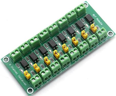
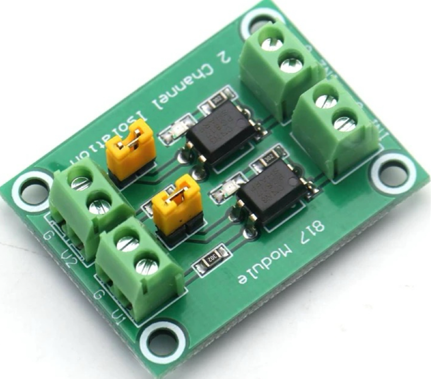
PC817 4 Channel Optocoupler Isolation Module Board
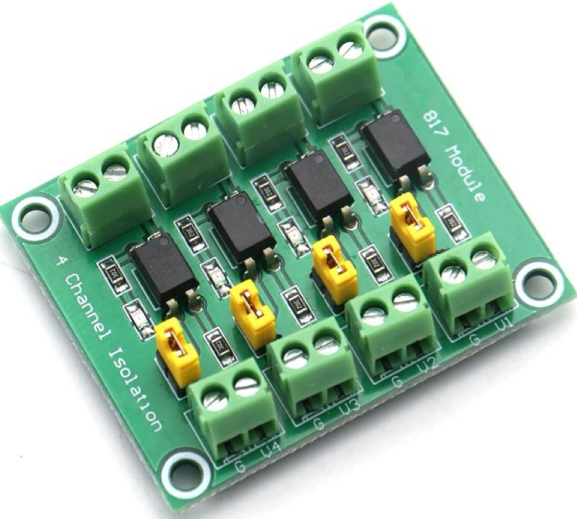
A 4-channel isolation board can use to provide multiple-channel isolation. This is especially useful when connecting to systems such as Arduino or Raspberry Pi, where multiple I/O lines need protection. It allows the safe and noise-free operation of sensors, relays, and other peripherals in high-voltage environments.
The PC817 Optocoupler Isolation Module design to provide electrical isolation between different sections of a circuit, typically in control and signal transmission systems. This module often use in applications that require isolated control, voltage conversion, and noise suppression. The optocoupler helps to transfer signals between circuits of different voltage levels while providing strong protection against electrical noise, transients, and high voltages.
This module can work with various voltage levels, such as 3.3V, 5V, and 24V, and is capable of isolating control signals from higher-power circuits.
Product Parameters:
Driver Signal Voltage: 3.6V – 24V
Output Voltage Range: 3.6V – 30V (maximum current: 10mA)
Jumper Caps: Allows output setting to high or low.
Each PC817 Independent: Allows simultaneous operation with different voltages on each channel.
Applications:
Use for isolating control signals from power systems, typically in industrial control, PLC systems, or microcontroller interfaces.
Use where different parts of a system operate at different voltage levels, such as interfacing 3.3V logic with 24V actuators.
Can drive MOSFETs or high-power transistors, providing electrical isolation while controlling high-voltage components.
Use for pulse signal transmission, especially where need voltage isolation between components, but with a frequency limitation of 4kHz.
Limitations: The module is not suitable for high-frequency pulse signals above 4kHz as the PC817’s frequency response limitation. Signals exceeding this frequency will result in improper operation or malfunction.
Frequently Asked Questions [FAQ] about Opto PC817
What is the alternative to PC817?
The 4N25, 4N35, 6N136, and 6N137 are popular alternatives to the PC817 optocoupler. These optocouplers offer similar isolation and voltage ratings but differ in their speed, current handling capabilities, or package types. For instance, the 6N137 often prefer for higher-speed applications, while the 4N35 offers better isolation. When selecting an alternative, should consider factors such as operating frequency, voltage isolation, and current handling capacity based on the specific requirements of the application.
Can PC817 be used for high frequency?
Not suitable for high-frequency applications as its low switching speed. PC817’s maximum operating frequency typically below 4kHz. Beyond this frequency, the performance deteriorates, causing signal distortion or malfunction. For applications requiring higher-frequency operation, alternatives such as the 6N137 or 6N136 optocouplers, which design for higher speeds (up to 10 MHz), should use to ensure proper functionality.
What is the difference between PC817 and 4N25 optocoupler?
Both provide electrical isolation, but they have differences in their specifications. The PC817 is typically rated for 50V collector-emitter voltage (Vce), whereas the 4N25 can handle 70V. The 4N25 also has a slightly higher switching speed compared to the PC817, making it more suitable for medium-speed applications. Additionally, the PC817 more commonly use in low-power control circuits, while the 4N25 use in industrial systems with higher voltage requirements.
What is the maximum voltage for PC817?
The maximum collector-emitter voltage (Vce) is typically 80V. This voltage rating indicates the maximum allowable voltage that can apply between the collector and emitter of the phototransistor without causing damage. Exceeding this voltage could lead to breakdown of the optocoupler’s isolation barrier, resulting in malfunction or failure. It is necessary to ensure that the voltage in the circuit does not exceed the rated voltage for reliable operation and to avoid damaging the component.
What is the difference between PC817 and 4N35?
Both offer electrical isolation but differ in their voltage ratings, speed, and packaging. The PC817 commonly use in low-speed, low-voltage applications with a maximum collector-emitter voltage of 80V. In contrast, the 4N35 design for slightly higher voltage isolation (up to 70V) and has a faster switching speed, making it more suitable for medium-speed applications. The 4N35 also has better current transfer ratio (CTR), making it more efficient for driving larger loads.
When should I use an optocoupler?
Should use when you need to isolate different sections of a circuit, particularly when those sections have different voltage levels or ground potentials. Common uses include protecting sensitive electronics from high voltages, preventing ground loops, or reducing noise in signal transmission. Optocouplers are useful for microcontroller interfacing, driving high-power components such as relays or transistors, and signal transmission in noisy environments. They also use in safety-critical applications to ensure electrical isolation and prevent damage from transients or surges.
What is the SMD equivalent of PC817?
The SMD (Surface-Mount Device) equivalents are EL816, LTV-816, LTV-817, PS2571-1. These comes in a compact surface-mount package, making it suitable for applications with space constraints and where through-hole mounting is impractical. The SMD package allows for easier integration in modern, compact electronic designs. When selecting the chip, it's key to verify the footprint and ensure compatibility with the circuit layout.
What is the cause of optocoupler failure?
The primary causes of failure include excessive current, voltage spikes, thermal stress, and incorrect component ratings. Overdriving the LED inside the optocoupler by using an incorrect current-limiting resistor can lead to overheating and damage. Voltage spikes or surges that exceed the optocoupler's maximum voltage ratings can break down the isolation barrier, causing failure. Thermal stress from poor heat dissipation or prolonged exposure to high temperatures can degrade the component. Additionally, electrostatic discharge (ESD) during handling or improper circuit design can also lead to failure.
Read More:
1. Guide To The XL6009 Boost Converter
HOT NEWS
Understanding A 0603 Resistor
0603 resistor,dimensions,marking code, values
2025-05-29
The 0402 Resistor: A Comprehensive Guide
0402 Resistor
2025-05-06
LR41 Battery Guide: Specifications, Equivalents, and Uses
LR41 Battery Specifications, Equivalents, and Uses
2025-12-14
MT3608 Boost Converter - An In-Depth Guide
MT3608 Boost Converter
2025-09-04
What Is A 1206 Resistor?
1206 resistor dimensions,footprint,value
2025-06-05
TP4056 Charging Module Pinout, Working, and Applications
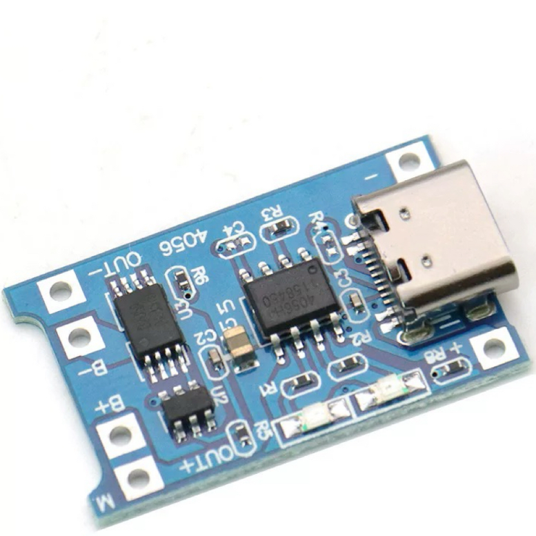
TP4056 Charging Module Pinout, Working, and Applications
2026-01-23
Everything You Need To Know About ARE1309 Relay
2025-04-23
Complete Guide to the 220 Ohm Resistor
220 Ohm Resistor
2025-07-28
120 Ohm Resistor- Specifications, Applications, and Features
2025-05-12
Guide To The XL6009 Boost Converter
XL6009 Boost Converter
2025-09-05