


 BOM
BOM Cart
Cart Product Catalog
The 2N3904 is one of the most popular NPN bipolar junction transistors (BJTs) use in electronics today. Known for its reliability, low cost, and versatility, this transistor widely use in switching, amplification, and signal processing applications. Its silicon epitaxial planar design provides stable performance, high gain, and fast switching, making it suitable for both educational projects and professional circuits.
In this guide, we will explore the 2N3904 pinout, specifications, features, equivalents, applications, dimensions, working principle, manufacturer overview, and frequently asked questions, providing a complete resource for engineers, hobbyists, and electronics enthusiasts.
2. 2N3904 Pinout, Symbol and Pin Configuration
3. Transistor 2N3904 Specifications
4. Features of the 2N3904 Transistor
5. Equivalent and Alternative Transistors to 2N3904
6. 2N3904 NPN Transistor Applications
7. Transistors 2N3904 Size Dimensions
8. 2N3904 Diode Working Principle and Circuit Example
9. IC 2N3904 Manufacturer Overview
10. Comparison Between Transistors 2N3904 and 2N2222
11. Frequently Asked Questions [FAQ]
What is the 2N3904?
A widely used NPN bipolar junction transistor (BJT) design for low-power switching and signal amplification applications. Make from silicon epitaxial planar technology, providing excellent performance, stability, and reliability in electronic circuits. The transistor operates as a current-controlled device, where a small base current allows a larger current to flow between the collector and emitter, enabling it to function as an electronic switch or amplifier.
This device can handle a maximum collector current of 200 mA, a collector-emitter voltage of 40 V, and a power dissipation of 625 mW, making it suitable for low- to medium-current applications. The 2N3904 offers high current gain (hFE), fast switching speed, and low saturation voltage, which makes it ideal for high-frequency and pulse circuits.
The chip use in amplifiers, oscillators, LED drivers, and digital logic circuits. As its affordability, availability, and reliability, it remains a preferred choice for engineers, students, and hobbyists in a wide range of electronic projects and learning applications.
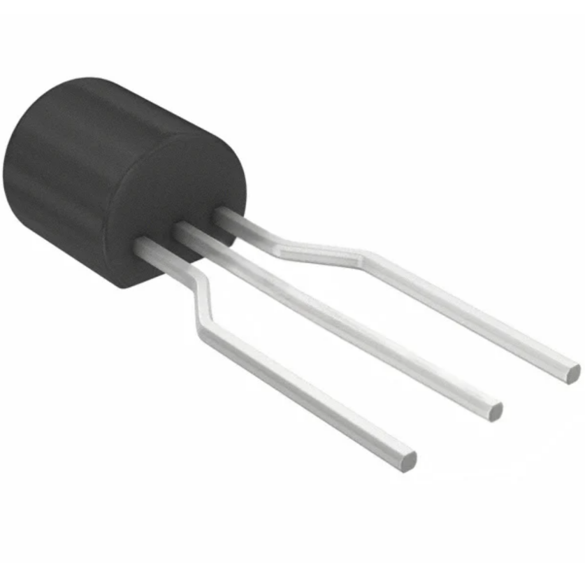
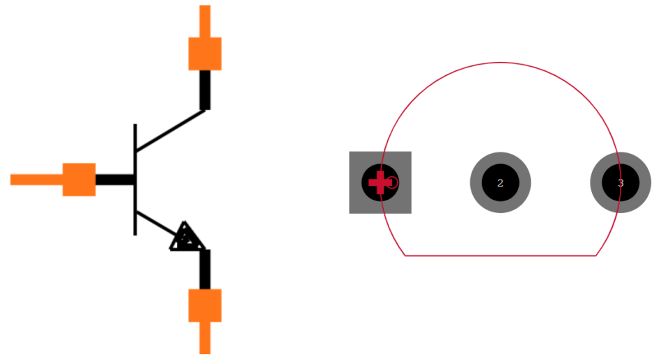
2N3904 Pinout, Symbol and Pin Configuration
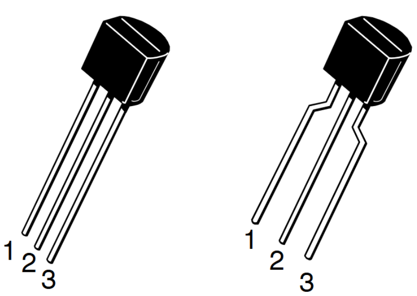
Pin-out (TO-92)
When facing the flat side of the TO-92 package with leads pointing downward, the pin configuration is:
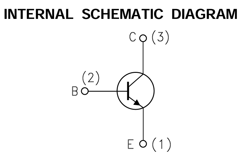
1. Emitter (E) – Current flows out of this terminal.
2. Base (B) – The control terminal that activates the transistor.
3. Collector (C) – The terminal through which the controlled current flows.
Symbol
Transistor 2N3904 Specifications
Below are the key electrical and thermal specifications that define its performance:
Transistor Type | NPN |
Current - Collector (Ic) (Max) | 200 mA |
Voltage - Collector Emitter Breakdown (Max) | 40 V |
Vce Saturation (Max) @ Ib, Ic | 300mV @ 5mA, 50mA |
DC Current Gain (hFE) (Min) @ Ic, Vce | 100 @ 10mA, 1V |
Power - Max | 625 mW |
Frequency - Transition | 300MHz |
Operating Temperature | -55°C ~ 150°C (TJ) |
Mounting Type | Through Hole/ Surface Mount |
Package / Case | TO-92-3/SOT-23-3 |
Base Product Number | 2N39 |
RoHS Status | ROHS3 Compliant |
ECCN | EAR99 |
These specifications make the circuit ideal for low- to medium-speed switching and signal amplification.
Features of the 2N3904 Transistor
2N3904 TO-92 Package:
Commonly use for through-hole PCB assembly, ideal for prototyping and educational projects as its easy handling and durability.
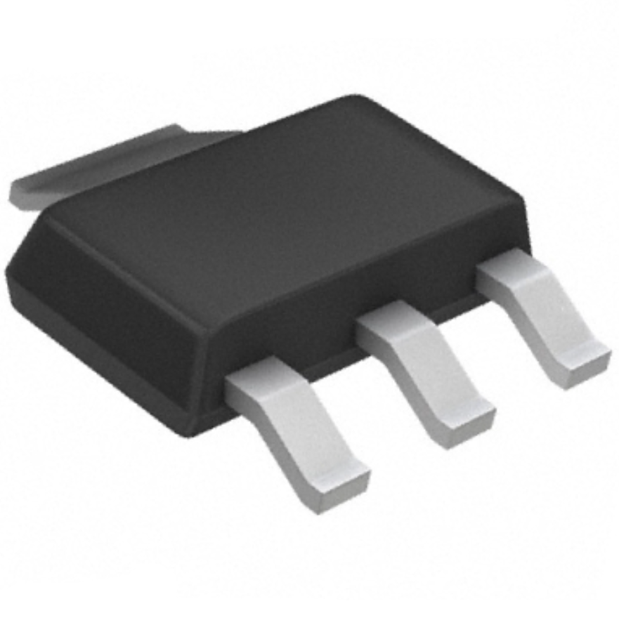
2N3904 SOT-23 Package (SMD / SMT):
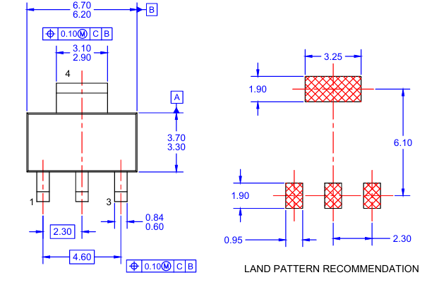
Surface mount version of the transistor, optimized for compact and automated PCB designs. It provides the same performance in a smaller form factor.
Silicon Epitaxial Planar NPN Design: Offers high stability, low noise, and good linearity, suitable for analog and digital applications.
High Gain and Low Saturation Voltage: Ensures efficient signal amplification and minimal power loss during switching.
Fast Switching Speed: Suitable for high-frequency circuits, such as pulse and digital switching systems.
Low Collector Current Leakage: Enhances performance stability and efficiency in low-power circuits.
Wide Availability and Low Cost: Readily available from multiple manufacturers, making it a go-to choice for designers, engineers, and hobbyists.
Equivalent and Alternative Transistors to 2N3904
The transistor has several replacement and substitute that can use depending on the required voltage, current, gain, and package configuration. These equivalents provide similar performance in amplification, switching, and general-purpose low-power applications.
Equivalent / Replacement Transistors
· BC547, BC537, BC538, BC549 BC636 BC639
· 2N2222, 2N2369, 2N3055, 2N3906, 2SC5200, P2N2222A
· BC537 and BC538 are functionally equivalent.
2N3904 Similar Transistor:
· 2N3904TA
· 2N3904BU
· 2N3904TF
· 2N3904TAR
· 2N3904TFR
When replacing a component, ensure the substitute has equal or higher voltage and current ratings, and confirm the pinout matches your circuit.
2N3904 NPN Transistor Applications
Signal Amplification:
Use in audio and radio frequency (RF) amplifier circuits to boost weak analog signals. Its high current gain ensures clean and efficient amplification with minimal distortion.
Switching Circuits:
Functions as a low-power switch in digital circuits, turning on and off small loads such as LEDs, buzzers, or relays. Its fast switching speed makes it ideal for pulse and timing circuits.
LED Driver and Indicator Circuits:
Commonly use to drive LEDs in display panels or visual indicators in appliances and electronic devices.
Oscillator and Timer Circuits:
Employed in oscillators, waveform generators, and timer circuits for signal generation or clock functions.
Home Appliance and TV Equipment:
Well-suited for use in control circuits, remote sensing modules, and signal processing units of televisions and small appliances.
Transistors 2N3904 Size Dimensions
The TO-92 package for traditional through-hole PCB mounting.
· Body width: 4.32 mm
· Body height: 5.33 mm
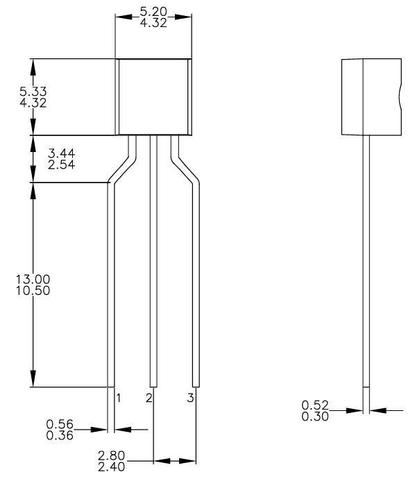
2N3904 Diode Working Principle and Circuit Example
The transistor can also function similarly to a diode under certain bias conditions because of its PN junctions. In an NPN transistor, there are two PN junctions — the base-emitter-junction and the base-collector-junction — which behave like diodes when forward-biased. This dual-junction structure allows the NPN transistor to control current flow, amplify signals, or act as a switch in circuits.
2N3904 Diode Working Principle
When the base-emitter junction is forward biased (base voltage is higher than emitter), the transistor allows current to flow from collector to emitter. In this state, it acts as a closed switch or conducting diode. When the base-emitter junction is reverse biased, no current flows, and the transistor behaves like an open circuit.
In essence, the transistor acts as a controllable diode — the base current determines whether it can flow through the collector-emitter path. This principle forms the basis of using 2N3904 for signal switching and LED control.
2N3904 LED Driver: Flash Circuit Example
A simple LED flash circuit can make using the transistor, a resistor, capacitor, and LED:
Components: 2N3904 transistor, 470Ω resistor, 100µF capacitor, LED, and 9V power source.
Working: The capacitor charges through the resistor, and when it reaches a threshold voltage, the transistor switches on, allowing current to flow through the LED, producing a flash. When the capacitor discharges, the transistor turns off, and the cycle repeats.
This circuit demonstrates how the 2N3904 acts as a switch and amplifier, controlling LED brightness and blinking frequency based on the RC timing network.
IC 2N3904 Manufacturer Overview
Manufacturers that produce this transistor include:
· Fairchild Semiconductor
· Motorola
· ON Semiconductor (Onsemi)
· NXP Semiconductors
Each brand maintains consistent specifications.
NPN 2N3904 Transistor Datasheet Download :
Specification Data Sheet PDF 2N3904 Datasheet Fairchild
Comparison Between Transistors 2N3904 and 2N2222
Specification | 2N3904 | 2N2222 |
Type | NPN | NPN |
Collector–Emitter Voltage (VCEO) | 40 V | 40 V |
Collector Current (IC) | 200 mA | 800 mA |
Power Dissipation | 625 mW | 1 W |
Gain (hFE) | 100 typical | 75 typical |
Frequency (fT) | 250 MHz | 250 MHz |
Package | TO-92, SOT-23 | TO-18, TO-92, SMD |
Summary:
The 2N2222 handles higher current and power, making it better for medium loads, while the 2N3904 is more suited for small-signal, low-current circuits.
Frequently Asked Questions [FAQ]
What is a 2N3904 transistor used for?
A general-purpose NPN transistor use for signal amplification, switching, and low-power electronic circuits. It can amplify weak analog signals in audio or RF applications, act as a switch to control LEDs, relays, or small motors, and interface digital logic circuits with larger loads. Its high gain, low saturation voltage, and fast switching speed make it suitable for both educational and professional electronics projects. It widely use in TV circuits, home appliances, oscillators, and microcontroller-driven circuits where small currents need to control larger currents efficiently.
Can I replace BC547 with 2N3904?
Yes, in most cases, can replace a BC547, as both are NPN general-purpose transistors with similar voltage, current, and gain ratings. Both are suitable for signal amplification and switching applications. However, designers should verify pin configuration and package type, since minor differences exist between TO-92 packages. While the electrical performance is similar, small variations in gain, maximum voltage, or leakage current could affect sensitive circuits. Checking the datasheets for both transistors ensures compatibility before replacement, particularly in high-frequency or precision analog applications.
What is the difference between 2N3904 and 2N2222?
Are both NPN transistors, but 2N2222 handles higher collector current (up to 600 mA) and higher power dissipation, making it suitable for medium-current switching. The 2N3904 limit to 200 mA and lower power, optimized for low-power, small-signal applications. Both have similar gain and frequency characteristics, but 2N3904 is more compact and widely use in signal amplification. The 2N2222 come in different packages (TO-18, TO-92, SMD), while the 2N3904 is available as TO-92 or SOT-23. Choice depends on current requirements and application type.
What is the equivalent of 2N3904?
Common equivalents include BC547, BC537, BC538, BC549, 2N2222, P2N2222A, and 2N2369. These transistors share similar electrical characteristics such as NPN type, collector current, voltage ratings, and gain, making them suitable for replacement in signal amplification and switching circuits. Functionally equivalent options include BC537 and BC538, which can substitute directly for low-power applications. When selecting a replacement, consider current rating, voltage rating, package type, and gain, ensuring compatibility with the existing circuit. Always confirm the pinout configuration before replacement.
What is the difference between 2N3904 and BC547?
Both 2N3904 and BC547 are NPN low-power transistors used for amplification and switching. The key differences include gain range, maximum current, and packaging variations. The 2N3904 has a collector current of 200 mA, whereas BC547 is limited to 100 mA. Both can handle voltages up to 40–45 V, but BC547 has lower noise, making it better for audio applications. Pin configuration vary slightly between manufacturers. Overall, 2N3904 is more commonly use in general-purpose circuits, while BC547 is favored in sensitive signal or low-noise designs.
What's the best way to test a 2N3904 transistor?
To test it, use a digital multimeter in diode or transistor test mode. Check the base-emitter and base-collector junctions, which should show a forward voltage drop of approximately 0.6–0.7 V when forward-biased. Reverse-biased measurements should read open circuit. In transistor mode, the multimeter can measure hFE (gain), indicating if the transistor is functional. Alternatively, build a simple test circuit with a resistor, LED, and power supply to verify switching behavior. Ensure correct pin identification: emitter, base, and collector; misconnection will give false readings.
What is the Beta Value of 2N3904?
The Beta (hFE) value of the transistor typically ranges from 100 to 300, depending on collector current and temperature. Beta represents the current gain, which is the ratio of collector current to base current. A higher Beta indicates greater amplification capability. In practical circuits, the Beta value helps determine the required base current to drive a specific collector current. Designers often use average Beta for calculation, while the actual gain vary across devices and operating conditions. The circuit provides reliable amplification for low-power signal processing.
How to setup a 2N3904 Transistor with Arduino?
To use a 2N3904 with an Arduino: connect the emitter to ground, the collector to the negative side of the load (such as an LED with series resistor), and the base to an Arduino digital output pin through a resistor (typically 220–1kΩ). When the Arduino pin outputs HIGH, current flows into the base, turning on the transistor and allowing collector-emitter current to drive the load. When the pin is LOW, the transistor switches off, stopping current flow. This setup enables the Arduino to control higher current devices safely using the transistor as a switch.
What is 2N3904 price?
The transistor is a low-cost, widely available component, making it ideal for hobbyists, students, and professionals. Prices vary depending on quantity, package, and supplier. Typically, a single 2N3904 transistor costs between $0.01 and $0.03 USD. Bulk purchases or reels for surface-mount versions can reduce the per-unit cost significantly. The affordability, combined with its versatility in switching and amplification applications, has made the circuit one of the most popular transistors in electronics projects worldwide.
Conclusion
The 2N3904 is a highly reliable, low-cost NPN transistor ideal for switching, signal amplification, and digital interfacing. With its availability in both TO-92 and SMD versions, it remains one of the most versatile components in electronics. Whether use for LED drivers, amplifiers, or basic transistor experiments, the 2N3904 continues to be a trusted choice for engineers, students, and hobbyists alike.
Read More:
1. ACS712 Current Sensor: An Overview and Guide
HOT NEWS
Understanding A 0603 Resistor
0603 resistor,dimensions,marking code, values
2025-05-29
The 0402 Resistor: A Comprehensive Guide
0402 Resistor
2025-05-06
LR41 Battery Guide: Specifications, Equivalents, and Uses
LR41 Battery Specifications, Equivalents, and Uses
2025-12-14
MT3608 Boost Converter - An In-Depth Guide
MT3608 Boost Converter
2025-09-04
What Is A 1206 Resistor?
1206 resistor dimensions,footprint,value
2025-06-05
TP4056 Charging Module Pinout, Working, and Applications
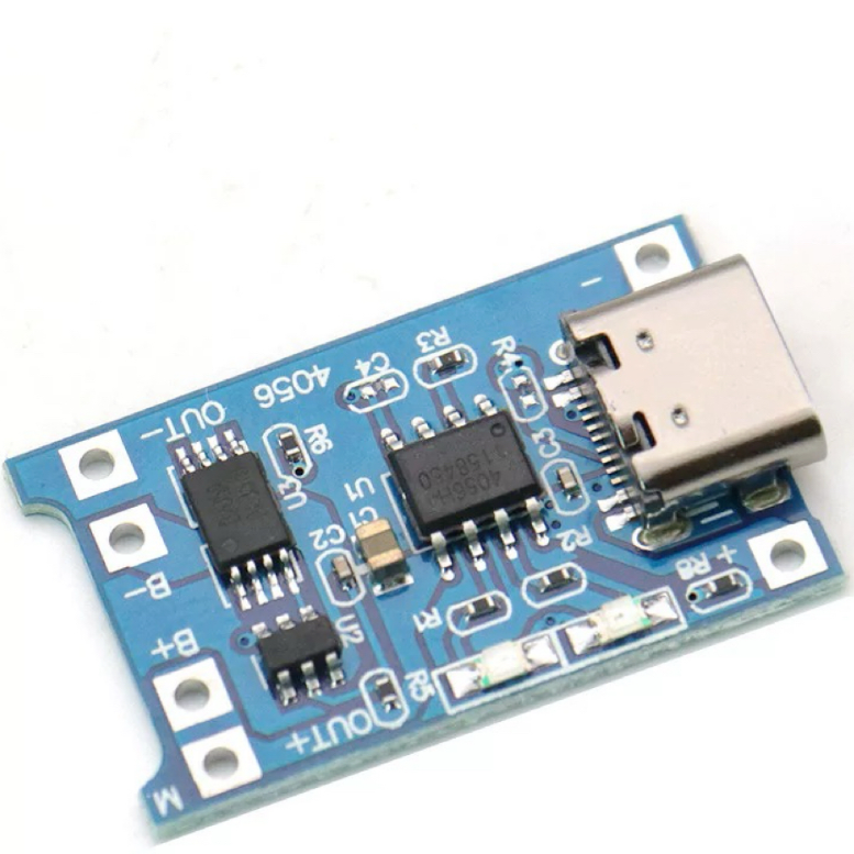
TP4056 Charging Module Pinout, Working, and Applications
2026-01-23
Everything You Need To Know About ARE1309 Relay
2025-04-23
Complete Guide to the 220 Ohm Resistor
220 Ohm Resistor
2025-07-28
120 Ohm Resistor- Specifications, Applications, and Features
2025-05-12
Guide To The AMS1117 Voltage Regulator
AMS1117 Voltage Regulator Circuit
2025-08-17