


 BOM
BOM Cart
Cart Product Catalog
The PIC18F25K20 is a low-power, high-performance 8-bit microcontroller from Microchip’s PIC18 family. Designed for power-sensitive embedded applications and combines flexible clock options, integrated peripherals, and Flash programmability in a compact package.
This article explains what the PIC18F25K20 is, its pin configuration, features, technical specifications, applications, package differences, and frequently asked questions.
2. PIC18F25K20 Pin Configuration, Pinout and Symbol
4. Specifications of PIC18F25K20
6. Difference Between PIC18F25K20-I/SS, PIC18F25K20-I/ML and PIC18F25K20-I/SO
7. Frequently Asked Questions [FAQ]
What Is a PIC18F25K20?
The PIC 18F25K20 is a low-power 8-bit microcontroller from Microchip’s PIC18 family, designed for embedded applications that require reliable performance and energy efficiency. It features 32 KB Flash program memory, 1.5 KB SRAM, and 256 bytes EEPROM, allowing flexible program storage and data retention. Operating over a wide voltage range from 1.8V to 3.6V, it supports battery-powered designs. The device integrates peripherals such as 10-bit ADC, timers, PWM modules, and serial communication interfaces (USART, SPI, I²C), making it suitable for control, monitoring, and communication tasks.
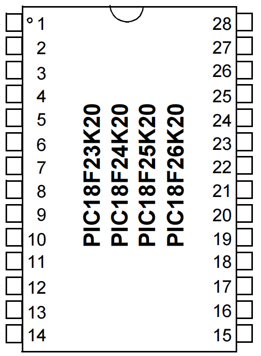
PIC18F25K20 Pin Configuration, Pinout and Symbol
The 18F25K20 is available in a 28-pin package and provides up to 25 general-purpose input/output (GPIO) pins, each supporting multiple alternate functions. This flexible pin multiplexing allows the microcontroller to handle analog inputs, digital I/O, communication interfaces, timers, and PWM outputs within a compact footprint.
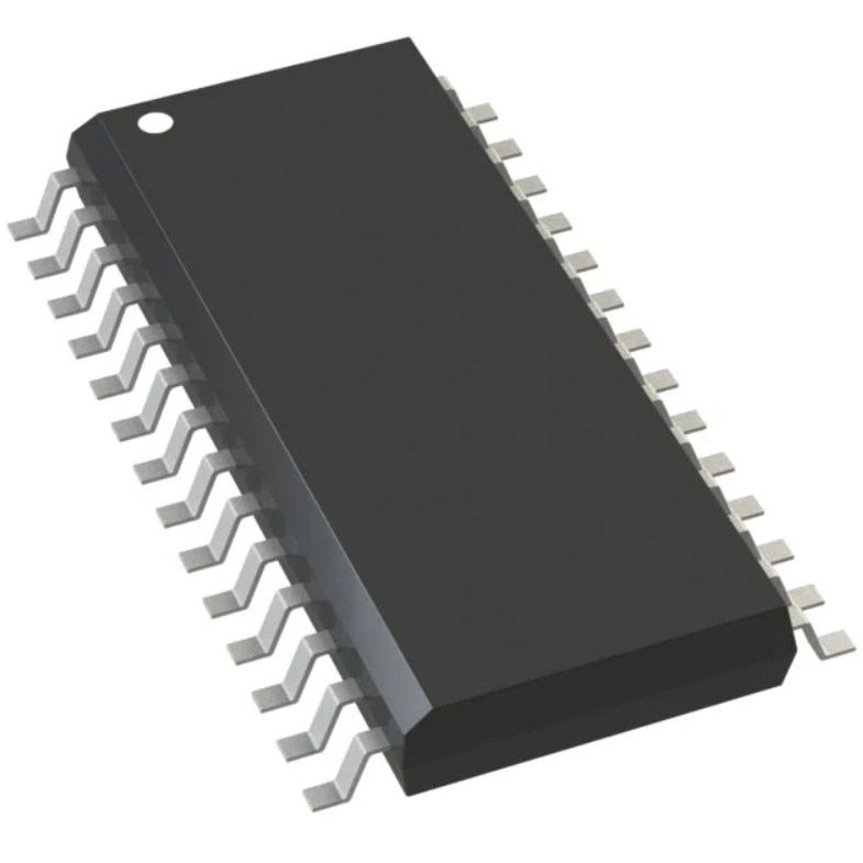
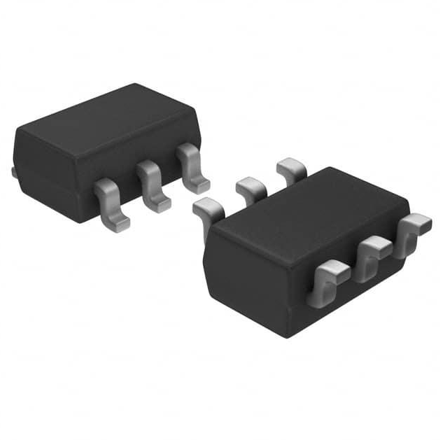
SSOP-28 SOIC-28 Package
The pinout is mostly identical for SSOP and SOIC, with all pins numbered 1–28. Key functions are:
Pin No. | Pin Name | Type | Description / Function |
1 | MCLR/VPP | Input | Reset / Programming voltage |
2–7 | RA0–RA5 | I/O / Analog | Digital I/O, AN0–AN4, special functions like T0CKI, SS |
8,19 | VSS | Ground | Ground |
9-10 | OSC1/OSC2 | Input/Output | External oscillator pins |
11-18 | RC0–RC7 | I/O | Digital I/O, CCP1/CCP2, UART, SPI, I²C |
20 | VDD | Power | Positive supply |
21–28 | RB0–RB7 | I/O | Digital I/O, interrupts, CCP2, weak pull-ups |
Note: SSOP is smaller than SOIC, while the pinout functions are the same.
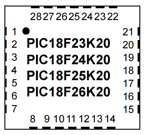
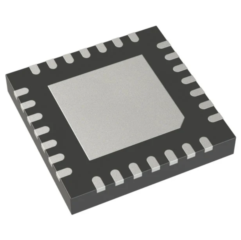
QFN-28 (ML version, Micro Lead Frame)
The QFN package uses bottom contacts (pads) instead of protruding pins. The functions are the same as SSOP/SOIC but with a different numbering system:
Pin No | Pin Name | Type | Description / Function |
1-4,27-28 | RA0–RA5 | I/O / Analog | Digital I/O, AN0–AN4 |
5,16 | VSS | Ground | Ground |
6,7 | OSC1/OSC2 | Input/Output | External oscillator |
8-15 | RC0–RC7 | I/O | Digital I/O, CCP, UART, SPI, I²C |
17 | VDD | Power | Positive supply |
18-25 | RB0–RB7 | I/O | Digital I/O, interrupts, CCP2, pull-ups |
26 | MCLR/VPP | Input | Reset / Programming voltage |
Center pad | VSS | Ground | Heat sink and electrical ground |
Note: QFN is much smaller and better for thermal performance, ideal for compact PCBs.
Summary of Package Differences
SSOP: Narrow, small footprint, harder to hand solder.
SOIC (SOP): Standard SMT, slightly larger, easier for assembly.
QFN (ML): Flat, leadless, minimal space, better heat dissipation, requires reflow soldering.
All three share the same pin functions and features, so the choice depends on PCB space, assembly method, and thermal requirements.
PIC18F25K20 Features
The microcontroller offers a comprehensive set of features that balance performance, flexibility, and low power consumption, making it suitable for a wide range of embedded applications.
At its core, the device base on the 8-bit PIC18 CPU architecture, which delivers efficient instruction execution and includes an 8×8 single-cycle hardware multiplier for faster arithmetic operations. The microcontroller supports clock speeds of up to 64 MHz using an internal Phase-Locked Loop (PLL), enabling it to handle time-critical control and communication tasks.
For memory resources, the chip integrates 32 KB of Flash program memory with self-write capability, 1.5 KB of SRAM for runtime data, and 256 bytes of EEPROM for non-volatile data storage. This combination allows firmware updates, parameter storage, and reliable data retention without external memory components.
Low-power operation is a key strength of this device. It operates over a wide voltage range of 1.8V to 3.6V and includes multiple power-saving modes such as Run, Idle, and Sleep. Additional features like the Watchdog Timer, Brown-Out Reset, and High/Low Voltage Detect improve system reliability in unstable power conditions.
The 18F25K20 also provides rich peripheral support. It includes a 10-bit Analog-to-Digital Converter (ADC) with multiple input channels for sensor interfacing, as well as Capture/Compare/PWM (CCP) and Enhanced CCP modules for precise timing and motor or LED control. Communication handle through integrated USART, SPI, and I²C interfaces, enabling easy connection to displays, sensors, memory devices, and other microcontrollers.
Together, these features make the circuit a versatile and dependable choice for embedded control, monitoring, and communication applications.
Specifications of PIC18F25K20
Parameter | Specification |
CPU Architecture | 8-bit PIC18 |
Operating Voltage | 1.8V – 3.6V |
Maximum Clock Speed | 64 MHz |
Flash Program Memory | 32 KB |
SRAM | 1,536 bytes |
EEPROM | 256 bytes |
ADC Resolution | 10-bit |
ADC Channels | Up to 11 |
Timers | 4 (8-bit and 16-bit) |
PWM Modules | CCP and Enhanced CCP |
Communication Interfaces | USART, SPI, I²C |
GPIO Pins | Up to 25 |
Operating Temperature | –40°C to +85°C |
Package Options | PDIP40, SOIC28, SSOP28, QFN28 |
Program Memory Type | FLASH |
Data Converters | A/D 11x10b |
Mounting Type | Surface Mount, Through-Hole |
Microchip PIC18F25K20 Datasheet PDF
PIC18F25K20 Applications
The component widely use in applications that require low power consumption and reliable performance, such as:
Industrial control systems
Used for monitoring and controlling industrial processes, handling sensors, actuators, and timing-based control tasks.
Battery-powered embedded devices
Suitable for portable and low-power designs because its low voltage operation and power-saving modes.
Consumer electronics
Applied in home appliances and electronic products for control, input handling, and basic signal processing.
Sensor monitoring and data acquisition
Reads and processes analog sensor data using its built-in ADC for measurement and monitoring systems.
Motor control and PWM-based systems
Generates PWM signals for controlling motor speed, fan operation, and LED brightness.
Communication interface modules
Acts as a communication controller using USART, SPI, and I²C interfaces.
Educational and development platforms
Commonly used in learning kits and development boards for teaching embedded system design.
Difference Between PIC18F25K20-I/SS, PIC18F25K20-I/ML and PIC18F25K20-I/SO
The PIC18F25K20-I/SS, PIC18F25K20-I/ML, and PIC18F25K20-I/SO are all variants of the same PIC18F25K20 microcontroller from Microchip. Functionally, they are identical—they have the same CPU, memory, peripherals, operating voltage, and electrical specifications. The only difference lies in their physical packaging, which affects how they mount on a PCB and the overall footprint on your circuit board.
Part Number | Package | Typical Use |
PIC18F25K20-I/SS | SSOP-28 | Smaller PCB footprints, compact designs |
PIC18F25K20-I/ML | QFN-28 | Easier hand soldering and prototyping |
PIC18F25K20-I/SO | SOIC-28 | Standard SMT, widely used in automated assembly |
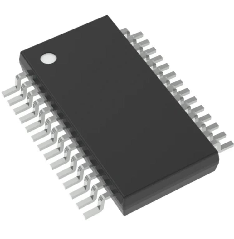
The PIC18F25K20-I/SS uses an SSOP (Shrink Small Outline Package). This package is narrow and compact, making it suitable for applications where PCB space is limited. However, its smaller size can make manual soldering a bit challenging.
The PIC18F25K20-I/ML comes in a QFN. It has a square form factor with pins on all four sides, which provides easier soldering for prototyping and slightly better heat dissipation compared to SSOP. This makes it a good choice for development boards or designs where require manual assembly.
The PIC18F25K20-I/SO uses a SOIC (Small Outline IC) package, which is a standard surface-mount package commonly used in automated production. It offers a balance between size and ease of assembly and widely support by PCB manufacturers.
In summary, the /SS, /ML, and /SO suffixes indicate the package type only, not the performance. Choosing the right package depends on your design requirements, PCB space, and whether you are hand-soldering prototypes or producing large quantities.
Frequently Asked Questions [FAQ]
What is the PIC18F25K20 used for?
The PIC18F25K20 is a versatile 8-bit microcontroller used in embedded systems for tasks such as motor control, sensor interfacing, data acquisition, and automation. Suitable for hobbyist projects, industrial applications, and consumer electronics. With its multiple I/O pins, timers, ADCs, and communication interfaces, it can handle a wide variety of control and monitoring functions efficiently.
What voltage does the PIC18F25K20 operate at?
The PIC18F25K20 operates over a wide voltage range, typically from 1.8V to 5.5V, making it flexible for low-power and standard logic-level applications. This allows designers to use it in battery-powered circuits or in systems with 3.3V or 5V logic without additional level-shifting components, ensuring compatibility across a broad spectrum of electronics projects.
Does the PIC18F25K20 support PWM?
Yes, the PIC18F25K20 supports Pulse Width Modulation (PWM) through its dedicated CCP (Capture/Compare/PWM) modules. PWM functionality allows precise control of motors, LEDs, and other devices requiring variable duty cycles. This makes it ideal for applications like speed control, dimming, signal generation, and power regulation in both industrial and hobbyist embedded systems.
Can the PIC18F25K20 be programmed in-circuit?
Yes, the PIC18F25K20 supports In-Circuit Serial Programming (ICSP), allowing the microcontroller to program directly on the PCB without removing it. Using Microchip programmers like the PICkit or MPLAB tools, developers can upload firmware, debug, and update the code efficiently. This feature simplifies development and reduces production errors in embedded system projects.
What is the PIC18F25K20 price?
The price of the PIC18F25K20 varies depending on the supplier, package type, and purchase volume. Typically, it ranges from $1 to $5 USD per unit for single quantities through electronics distributors. Bulk orders or sourcing from manufacturers reduce the price further. Prices also fluctuate as market availability and shipping costs.
Conclusion
The PIC18F25K20 IC Chip is a versatile 8-bit microcontroller that combines low power consumption, flexible clock options, and rich peripheral integration. Its balance of performance and efficiency makes it suitable for a wide range of embedded applications, from industrial control to consumer electronics.
Read More:
1. LM393: Guide to the Dual Comparator IC
2. FT232: The Ultimate USB to UART Solution
3. LM317T Voltage Regulator: Pinout, Datasheet and Equivalent
HOT NEWS
Understanding A 0603 Resistor
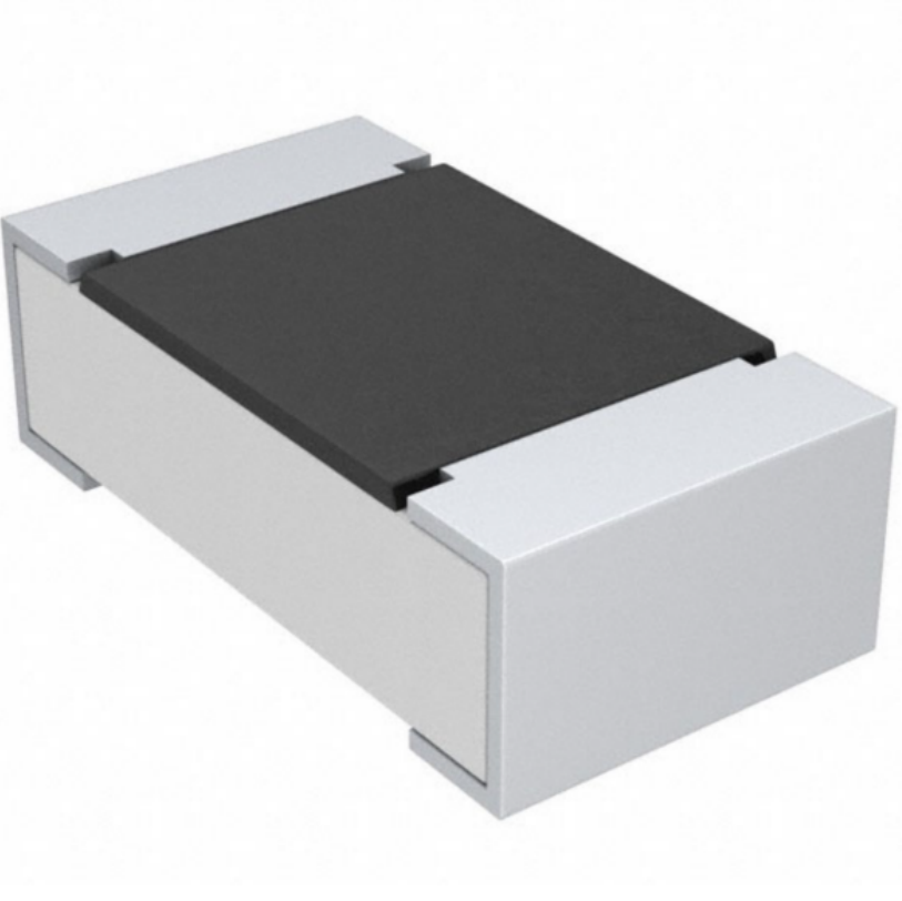
0603 resistor,dimensions,marking code, values
2025-05-29
The 0402 Resistor: A Comprehensive Guide
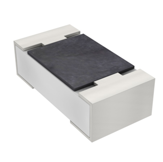
0402 Resistor
2025-05-06
LR41 Battery Guide: Specifications, Equivalents, and Uses
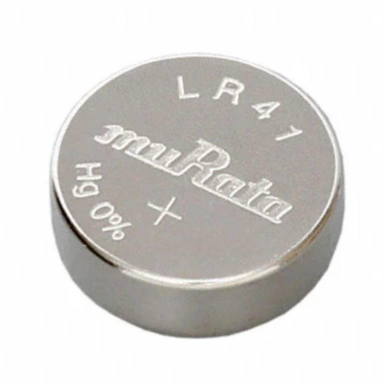
LR41 Battery Specifications, Equivalents, and Uses
2025-12-14
MT3608 Boost Converter - An In-Depth Guide
MT3608 Boost Converter
2025-09-04
What Is A 1206 Resistor?
1206 resistor dimensions,footprint,value
2025-06-05
TP4056 Charging Module Pinout, Working, and Applications
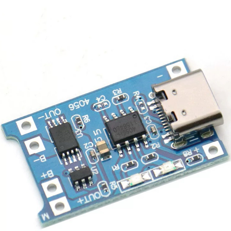
TP4056 Charging Module Pinout, Working, and Applications
2026-01-23
Everything You Need To Know About ARE1309 Relay
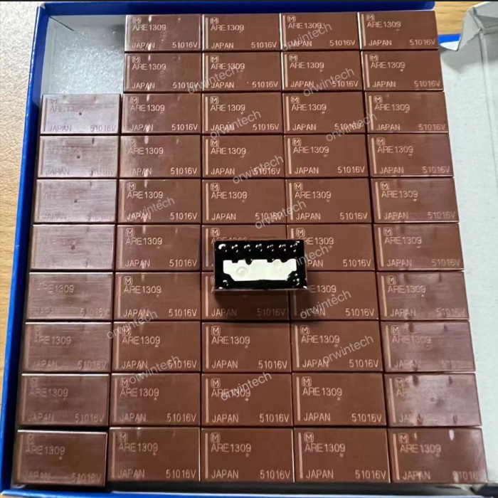
2025-04-23
Complete Guide to the 220 Ohm Resistor
220 Ohm Resistor
2025-07-28
120 Ohm Resistor- Specifications, Applications, and Features
2025-05-12
Guide To The AMS1117 Voltage Regulator
AMS1117 Voltage Regulator Circuit
2025-08-17