


 BOM
BOM Cart
Cart Product Catalog
The IR2104 is a high-voltage, high-speed gate driver IC designed to drive N-channel MOSFETs and IGBTs in half-bridge configurations. Manufactured by Infineon Technologies, the IR 2104 integrates both high-side and low-side gate drivers into a single compact package, simplifying the design of motor drives, power inverters, switching power supplies, induction heating systems, and other power electronics applications.
Featuring a floating high-side channel capable of operating up to 600V, the IR 2104 uses bootstrap technology to efficiently drive high-side switching devices. The IC includes built-in undervoltage lockout protection, cross-conduction prevention logic, matched propagation delays, and internally fixed dead time to improve system reliability and prevent shoot-through currents. Its compatibility with 3.3V, 5V, and 15V logic levels makes it suitable for modern microcontroller and digital control systems.
This article explores the circuit in detail, covering its features, specifications, pin configuration, working principle, electrical characteristics, applications, equivalent devices, and comparison with the IR2101 gate driver IC.
1. What is IR2104 Half-Bridge Driver?
2. Key Features and Technical Specifications
3. Pin Details and Configuration
7. Recommended Working Conditions
9. Comparison Between IR2104 and IR2101
10. Frequently Asked Questions [FAQ]
What is IR2104 Half-Bridge Driver?
The IR2104 and IR2104S are high-voltage, high-speed gate driver ICs designed to drive power MOSFETs and IGBTs in half-bridge configurations. Developed by Infineon Technologies, the device integrates both high-side and low-side gate drivers into a single package, simplifying the design of motor drives, inverters, switching power supplies, and industrial power control systems.
The IR2104 utilizes proprietary HVIC (High Voltage Integrated Circuit) and latch-immune CMOS technologies, providing rugged monolithic construction and reliable operation in harsh electrical environments. The logic inputs are compatible with standard CMOS and LSTTL outputs, including modern 3.3V logic systems.
A bootstrap architecture allows the high-side channel to drive an N-channel MOSFET or IGBT operating at voltages from 10V up to 600V. The integrated dead-time and cross-conduction prevention logic help prevent shoot-through currents in half-bridge circuits, increasing system reliability and efficiency.
Whether you are designing a BLDC motor controller, inverter, induction heating system, or high-frequency switching converter, the IR 2104 provides an efficient and cost-effective gate-driving solution.
IR2104 Key Features and Technical Specifications
Bootstrap High-Side Operation: The component features a floating channel designed for bootstrap operation, allowing it to efficiently drive high-side N-channel MOSFETs or IGBTs in half-bridge circuits.
High Voltage Capability: The device is fully operational with high-side voltages up to 600V, making it suitable for high-voltage power conversion and motor control applications.
Negative Transient Voltage Tolerance: Design to withstand negative transient voltages that commonly occur in switching power circuits, improving reliability under harsh operating conditions.
High dV/dt Immunity: Excellent dV/dt immunity helps prevent false triggering and ensures stable operation in high-speed switching environments.
Wide Gate Drive Supply Range: The gate driver operates from a supply voltage range of 10V to 20V, providing flexibility for various MOSFET and IGBT gate drive requirements.
Undervoltage Lockout Protection (UVLO): Built-in undervoltage lockout prevents the driver from operating when the supply voltage is low, protecting power devices from improper switching.
Logic-Level Compatibility: The input logic is compatible with 3.3V, 5V, and 15V control signals, enabling easy interfacing with microcontrollers, DSPs, FPGAs, and digital control circuits.
Cross-Conduction Prevention Logic: Integrated shoot-through protection logic helps prevent both high-side and low-side switches from turning on simultaneously.
Internally Fixed Dead Time: The built-in dead time simplifies circuit design and improves switching safety by minimizing the risk of cross-conduction.
Non-Inverting High-Side Output: The high-side output operates in phase with the input signal, simplifying control logic implementation.
Shutdown Function: An active-low shutdown input allows both output channels to be turned off instantly for system protection and fault handling.
Matched Propagation Delays: Closely matched propagation delays between the high-side and low-side outputs ensure consistent switching performance.
Lead-Free Availability: The IR 2104 is available in environmentally friendly lead-free packages, meeting modern manufacturing and regulatory requirements.
Technical Specifications
Parameter | Value |
Manufacturer | Infineon Technologies |
Driven Configuration | Half-Bridge |
Number of Drivers | 2 |
Input Type | Non-Inverting |
Gate Type | N-Channel MOSFET, IGBT |
High-Side Voltage | 600V Maximum |
Supply Voltage | 10V to 20V |
Peak Source Current | 210mA |
Peak Sink Current | 360mA |
Rise Time | 100ns Typical |
Fall Time | 50ns Typical |
Logic Input Low (VIL) | 0.8V |
Logic Input High (VIH) | 3.0V |
Operating Temperature | -40°C to +150°C |
Mounting Type | Through Hole |
Package | DIP-8 |
Package/Case | 8-PDIP |
Base Product Number | IR2104 |
IR2104 Pin Details and Configuration
The IR2104 is available in an 8-pin package and includes dedicated pins for both the high-side and low-side drivers.
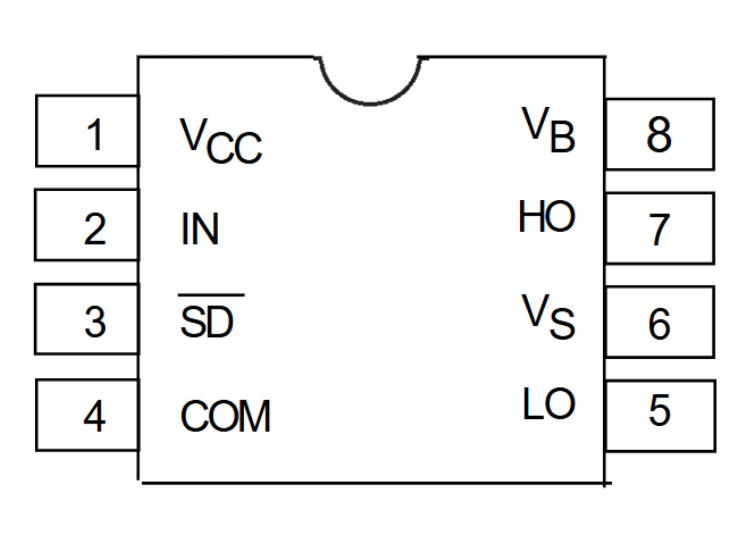
Pin No. | Pin Name | Function |
1 | VCC | Supplies power to the internal logic circuitry and gate driver stages. |
2 | IN | Control input used to determine the switching state of the driver outputs. |
3 | SD | Active-low shutdown input that disables both the high-side and low-side outputs when pulled low. |
4 | COM | Common ground reference for the logic section and low-side driver. |
5 | LO | Output pin used to drive the gate of the low-side MOSFET or IGBT. |
6 | VS | Floating return connection for the high-side driver, typically connected to the switching node. |
7 | HO | Output pin that drives the gate of the high-side MOSFET or IGBT. |
8 | VB | Floating bootstrap supply input that powers the high-side gate driver. |
Pin Function Overview
VCC
Provides power for the internal logic circuitry and gate drivers. Typical operating voltage is between 10V and 20V.
IN
Controls the switching state of the high-side and low-side outputs.
SD
An active-low shutdown input. Pulling this pin low disables both output drivers.
COM
Ground reference for the low-side driver and logic section.
LO
Output for driving the low-side MOSFET gate.
VS
Floating return node connected to the switching node of the half-bridge.
HO
Output used to drive the high-side MOSFET gate.
VB
Bootstrap supply voltage for the high-side gate driver.
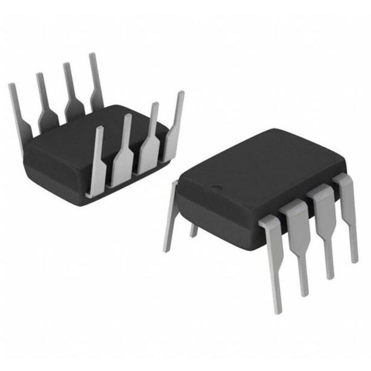
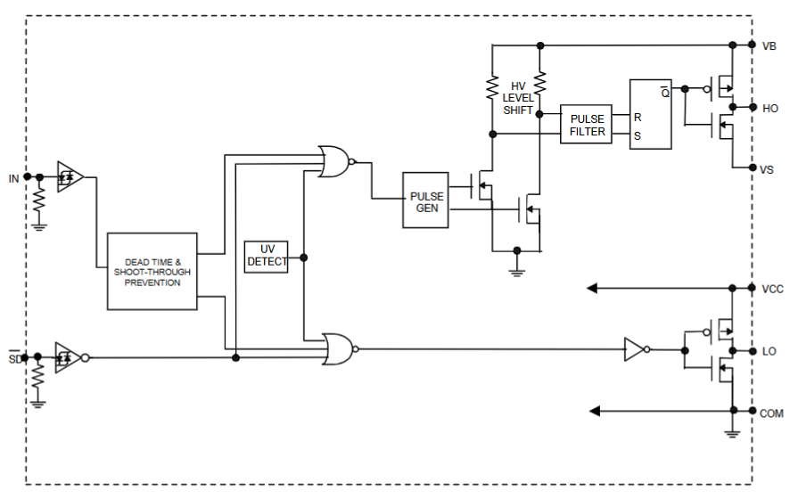
Functional Block Diagram of IR2104
Physical Package of IR2104
Commonly available in:
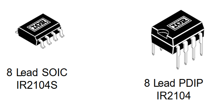
· DIP-8 (PDIP-8)
· SOIC-8 (IR2104S)
The DIP version is popular for prototyping and educational projects, while prefer the SOIC version for compact PCB designs.
IR2104 Equivalent
Can use several alternative half-bridge driver ICs as replacements depending on application requirements.
DGD2104
The DGD2104 is a non-inverting half-bridge gate driver that provides functionality similar to the IR 2104. It supports high-side and low-side MOSFET driving and is commonly available in an 8-pin SO package.
IR2101S
The IR2101S is a half-bridge gate driver IC designed for driving N-channel MOSFETs and IGBTs. It supports high-voltage operation up to 600V and comes in an 8-pin SOIC package.
IR2103
The IR2103 offers both inverting and non-inverting drive options, providing greater flexibility for different switching topologies. It is available in an 8-pin PDIP package and is suitable for motor control and power conversion applications.
IRS2104
The IRS2104 is a direct replacement for the IR2104 in many designs. It features similar electrical characteristics, built-in dead time, and half-bridge gate driving capability while maintaining pin compatibility.
IR2153
The IR2153 combines a half-bridge gate driver with an integrated RC oscillator. This makes it particularly useful for electronic ballasts, resonant converters, and self-oscillating power supply designs.
IR2110
The IR2110 is a more advanced high-side and low-side gate driver that provides independent control inputs and higher output drive capability. Available in a 14-pin DIP package, widely used in high-power inverters, motor drives, and industrial power electronics systems.
IR2104 Working Principle
The IR2104 operates as a half-bridge gate driver by controlling two N-channel MOSFETs arranged in a high-side and low-side configuration.
When the input pin is driven high:
· The high-side driver output (HO) turns on.
· The low-side driver output (LO) turns off.
· Current flows through the high-side MOSFET.
When the input pin is driven low:
· The high-side MOSFET turns off.
· The low-side MOSFET turns on.
· Current returns through the low-side switch.
A bootstrap capacitor connected between VB and VS supplies the floating voltage needed to drive the high-side MOSFET gate above the source voltage.
The internally generated dead time prevents both MOSFETs from conducting simultaneously, avoiding destructive shoot-through currents.
Maximum Electrical Ratings of IR2104
Table
Symbol | Definition | Min | Max |
VB | High-side floating voltage | -0.3V | 625V |
VS | Floating supply offset voltage | VB-25V | VB+0.3V |
VHO | High-side output voltage | VS-0.3V | VB+0.3V |
VCC | Logic supply voltage | -0.3V | 25V |
VLO | Low-side output voltage | -0.3V | VCC+0.3V |
VIN | Input voltage (IN, SD) | -0.3V | VCC+0.3V |
dVS/dt | Offset voltage transient | — | 50V/ns |
PD (PDIP) | Package power dissipation | — | 1W |
PD (SOIC) | Package power dissipation | — | 0.625W |
RθJA (PDIP) | Thermal resistance | — | 125°C/W |
RθJA (SOIC) | Thermal resistance | — | 200°C/W |
TJ | Junction temperature | — | 150°C |
TS | Storage temperature | -55°C | 150°C |
TL | Soldering temperature | — | 300°C |
Recommended Working Conditions for IR2104
For reliable long-term operation, designers should follow these guidelines:
Supply Voltage (VCC)
The recommended gate drive supply voltage is 10V to 20V. This range ensures proper MOSFET or IGBT gate enhancement without risking over-voltage stress on the driver IC.
Logic Input Voltage
The input control signal (IN and SD pins) should be compatible with 3.3V, 5V, or 15V logic levels, with proper high and low thresholds maintained for reliable switching.
High-Side Operating Voltage
The floating high-side supply can operate up to 600V, but system design should include proper margin and protection against voltage spikes and transients.
Operating Temperature
The safe junction operating temperature range is -40°C to +125°C (recommended) for reliable long-term operation, although the absolute maximum junction temperature is up to 150°C.
Bootstrap Supply Conditions
Require a properly selected bootstrap capacitor (typically 100nF to 1µF) and fast recovery diode to maintain stable high-side gate drive operation.
Switching Frequency
The IR2104 is suitable for medium to high-frequency switching applications, typically up to tens of kHz, depending on MOSFET size, gate charge, and thermal design.
PCB and Layout Requirements
· Keep gate drive traces short and wide
· Use proper grounding for COM and power return
· Place bootstrap capacitor close to VB and VS pins
· Minimize parasitic inductance in half-bridge loop
Thermal Considerations
Ensure adequate heat dissipation and respect power dissipation limits:
· PDIP package: up to ~1W at 25°C
· SOIC package: lower thermal limit (~0.625W)
Summary
For best performance, the IR2104 should be operated with:
· VCC: 10V–20V
· Logic: 3.3V–15V compatible signals
· Temperature: ideally below 125°C junction
· Proper bootstrap and PCB layout design for stable high-side driving
These conditions help ensure efficient, reliable, and noise-immune operation in half-bridge power electronics systems.
IR2104 Applications
Motor Drivers
Used extensively in DC, BLDC, and AC motor control systems where require efficient MOSFET switching.
Inverters
Commonly found in pure sine wave and modified sine wave inverter circuits for renewable energy and UPS systems.
Switching Power Supplies
Provides high-speed gate control for half-bridge and full-bridge SMPS topologies.
Induction Heating
Drives high-power MOSFETs used in induction cookers and industrial heating equipment.
Solar Power Systems
Used in DC-AC conversion stages of solar inverters.
UPS Systems
Controls switching transistors in backup power and uninterruptible power supply circuits.
Welding Equipment
Supports high-voltage power conversion circuits found in inverter welding machines.
Industrial Automation
Used in servo drives, motion controllers, and industrial motor control platforms.
Comparison Between IR2104 and IR2101
Table
Parameter | IR2104 | IR2101 |
Manufacturer | Infineon Technologies | Infineon Technologies |
Driver Type | Half-Bridge | Half-Bridge |
Input Type | Non-Inverting | Non-Inverting |
High-Side Voltage | 600V | 600V |
Supply Voltage | 10V to 20V | 10V to 20V |
Peak Source Current | 210mA | 210mA |
Peak Sink Current | 360mA | 360mA |
Rise Time | 100ns | 100ns |
Fall Time | 50ns | 50ns |
Operating Temperature | -40°C to 150°C | -40°C to 150°C |
Package | DIP-8 | DIP-8 |
Number of Drivers | 2 | 2 |
Logic Compatibility | 3.3V / 5V | 3.3V / 5V |
Internal Dead Time | Yes | No |
Cross-Conduction Prevention | Yes | Limited |
Key Difference
The IR2104 is designed with internal dead-time generation and stronger cross-conduction prevention, which makes it more robust in real half-bridge switching conditions. This reduces the need for precise external timing control and significantly lowers the risk of shoot-through damage in MOSFET or IGBT stages.
In contrast, the IR2101 offers a more basic driver structure without built-in dead-time. This means the designer must carefully manage switching timing using external circuitry or MCU control. While this adds complexity, it also provides greater flexibility for custom timing strategies in advanced power electronics designs.
Another practical difference is in system reliability: the IR2104 is generally preferred in mass-production and safety-critical applications because it reduces design errors and improves consistency. The IR2101 is more suitable for experienced designers who want full control over switching behavior and can implement precise dead-time management externally.
Overall, the IR 2104 prioritizes simplicity, protection, and reliability, while the IR2101 emphasizes control flexibility and design freedom.
IR2104 Datasheet PDF
The data sheet provides complete information regarding:
· Electrical characteristics
· Timing diagrams
· Application circuits
· Bootstrap design calculations
· Thermal specifications
· Package dimensions
· PCB layout recommendations
Engineers should always consult the latest datasheet before finalizing a design.
Frequently Asked Questions [FAQ]
What is IR2104 price?
The IR 2104 is generally an inexpensive gate driver IC. Pricing typically ranges from approximately $0.40 to $3.00 per unit depending on quantity, package type, and supplier.
What is the use of IR2110?
The IR2110 is a high- and low-side MOSFET/IGBT driver used in inverters, motor drives, UPS systems, induction heating equipment, and high-power switching applications requiring independent control of both channels.
What is a half-bridge gate driver?
A half-bridge gate driver controls a pair of power transistors arranged in a high-side and low-side configuration. It provides level shifting, isolation of control signals, and sufficient gate drive current for efficient switching.
How is the IRS2104 different from the IR2104?
The IRS2104 is a newer version with similar functionality and pin compatibility. It typically offers improved manufacturing processes, better availability, and enhanced reliability while maintaining the same operating principles.
Why is the IR2104 MOSFET driver not working?
Common causes include insufficient bootstrap voltage, incorrect MOSFET wiring, inadequate gate drive supply, poor PCB layout, missing decoupling capacitors, or improper grounding between COM and the control circuit.
What is the difference between IR2110 and IR2104?
The IR2110 provides independent control inputs for both high-side and low-side outputs and offers higher drive capability. The IR2104 uses a single non-inverting input with built-in dead-time for simpler half-bridge applications.
What is the maximum voltage of IR2104?
The IR 2104 supports high-side operation up to 600V and can tolerate a floating voltage of up to 625V on the bootstrap supply node.
What is the equivalent IC of IR2104?
Common alternatives include IRS2104, DGD2104, IR2101S, IR2103, IR2153, and IR2110. The best replacement depends on drive current requirements, package type, and control architecture.
Conclusion
The IR2104 Half-Bridge Gate Driver IC is a reliable and widely used solution for driving high-side and low-side MOSFETs or IGBTs in power electronics applications. With its 600V capability, built-in dead-time, undervoltage lockout, cross-conduction protection, and compatibility with 3.3V and 5V logic systems, it simplifies the design of motor drives, inverters, SMPS circuits, and industrial power converters. Its compact 8-pin package and straightforward bootstrap operation make the component an excellent choice for both hobbyist and professional power electronics designs.
Read More:
1. MT3608 Boost Converter - An In-Depth Guide
HOT NEWS
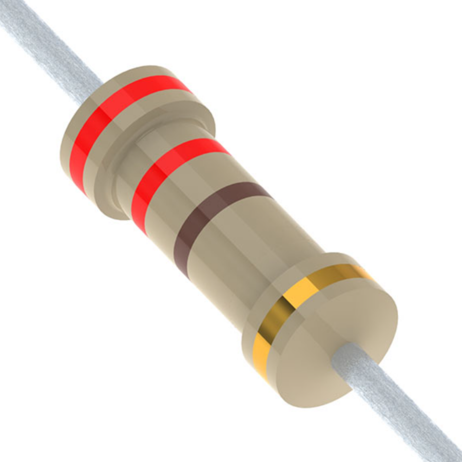
Understanding A 0603 Resistor
0603 resistor,dimensions,marking code, values
2025-05-29
The 0402 Resistor: A Comprehensive Guide
0402 Resistor
2025-05-06
MT3608 Boost Converter - An In-Depth Guide
MT3608 Boost Converter
2025-09-04
What Is A 1206 Resistor?
1206 resistor dimensions,footprint,value
2025-06-05
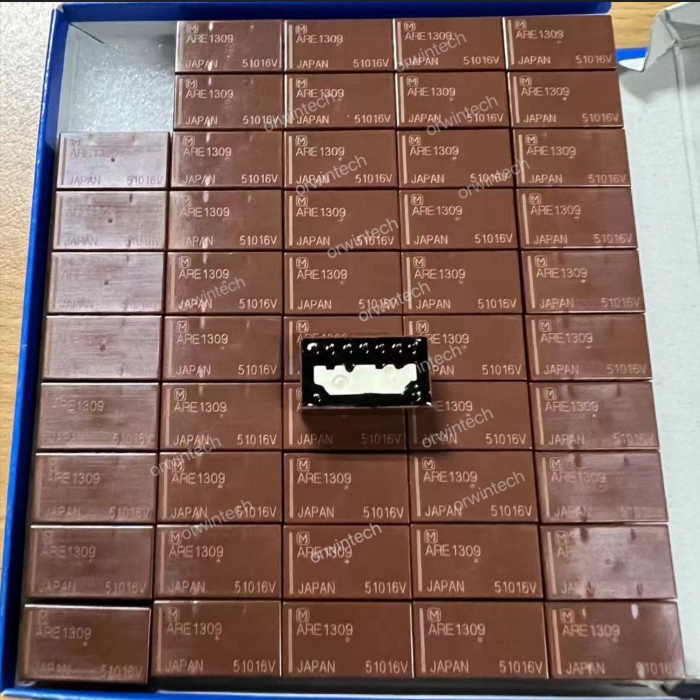
Everything You Need To Know About ARE1309 Relay
2025-04-23
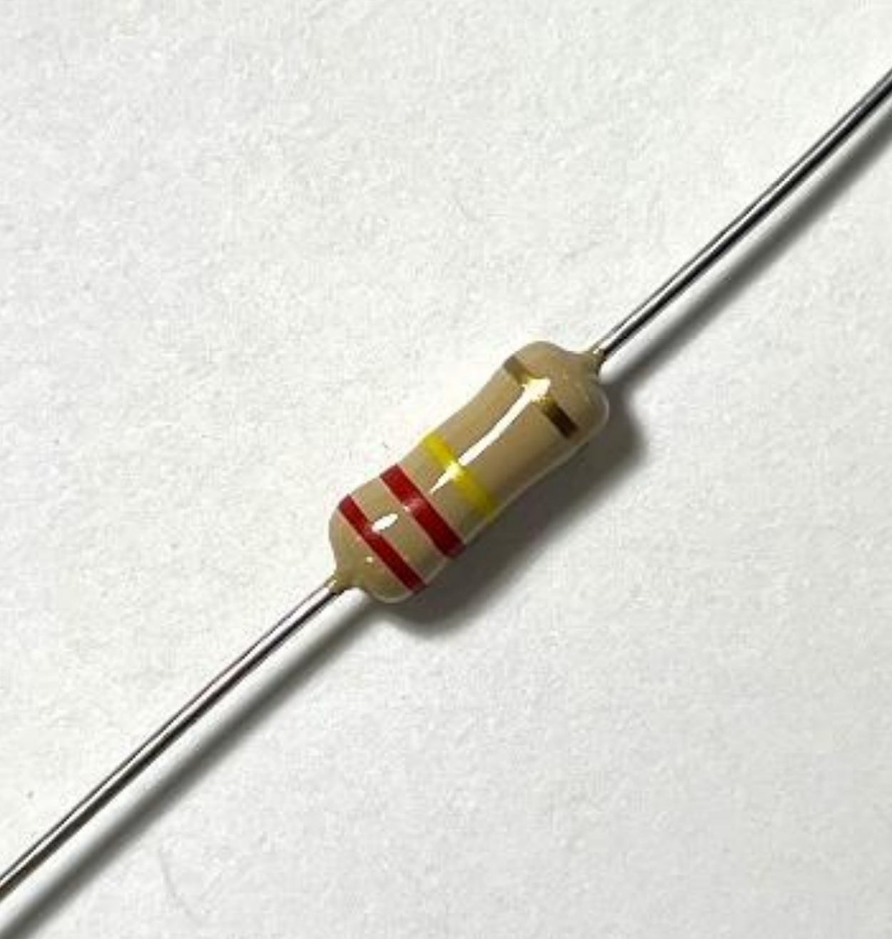
Complete Guide to the 220 Ohm Resistor
220 Ohm Resistor
2025-07-28
TP4056 Charging Module Pinout, Working, and Applications
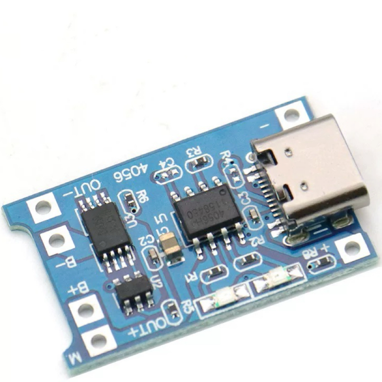
TP4056 Charging Module Pinout, Working, and Applications
2026-01-23
120 Ohm Resistor- Specifications, Applications, and Features
2025-05-12
What is 10k Ohm Resistor?
10k resistor 10k resistor color code
2025-05-14
Guide To The AMS1117 Voltage Regulator
AMS1117 Voltage Regulator Circuit
2025-08-17