




 BOM
BOM Cart
Cart Product Catalog
The MAX7219 is one of the most popular LED display driver ICs used in Arduino, Raspberry Pi, STM32, ESP32, and 8051 microcontroller projects. It simplifies the control of 8×8 LED matrices, 7-segment displays, and LED bar graphs by requiring only three control signals. The built-in scanning circuit and brightness control eliminate display flickering while significantly reducing the number of microcontroller I/O pins required.
Whether you're building a scrolling text display, digital clock, sensor dashboard, or animation project, the MAX 7219 module offers a reliable and easy-to-use solution.
1. What is the MAX7219 Module?
7. How to Program MAX7219 8x8 Display Driver IC?
8. Connecting Multiple Display Modules
9. Frequently Asked Questions [FAQ]
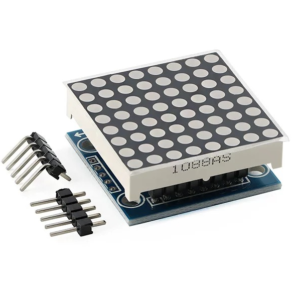
What is the MAX7219 Module?
The MAX 7219 is an integrated serial input/output display driver designed for controlling common-cathode LED displays. It can drive 8-digit 7-segment displays, 8×8 LED dot matrix modules, bar graph displays, or up to 64 individual LEDs. The chip integrates a BCD decoder, multiplex scan circuitry, segment drivers, and an 8×8 static RAM for display data storage. A single external resistor sets the LED segment current, while the built-in serial interface simplifies communication with most microcontrollers. It also features adjustable digital and analog brightness control, a low-power 150 μA shutdown mode, display test mode, scan-limit control, flicker-free multiplexing, and supports cascading multiple modules using only three microcontroller I/O pins.
MAX7219 8x8 LED Module Technical Specifications
Table
Parameter | Value |
Driver IC | MAX 7219 |
Display Type | 8×8 Common Cathode LED Matrix |
Operating Voltage | 5V DC |
Control Interface | SPI-like Serial |
Communication Pins | DIN, CS, CLK |
LED Matrix Size | 8×8 (64 LEDs) |
Module Dimensions | 32 × 32 × 13 mm |
Mounting Hole Diameter | 3 mm |
Mounting Holes | 4 |
Cascading Support | Yes |
Display RAM | 8×8 Static RAM |
Brightness Control | 16 Levels |
Shutdown Current | Approximately 150 μA |
MAX7219 LED Matrix Module Pinout
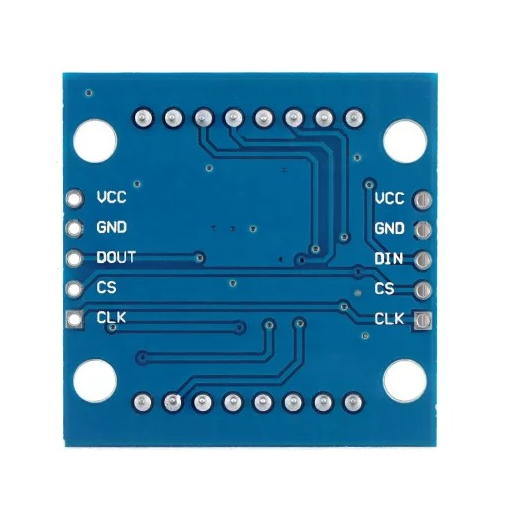
Pin Number | Pin Name | Function |
1, 6 | VCC | 5V Power Input/Output |
2, 7 | GND | Ground Input/Output |
3 | DIN | Serial Data Input |
4, 9 | CS | Chip Select (Load Signal) |
5, 10 | CLK | Serial Clock Input |
8 | DOUT | Serial Data Output for Cascading |
Pin Description
VCC
Supplies 5V power to the module and also passes power to the next cascaded module.
GND
Common ground connection for both power input and output.
DIN
Receives serial display data from the microcontroller.
CS (LOAD)
Chip Select pin used to latch incoming serial data into the MAX 7219 registers.
CLK
Clock signal that synchronizes serial communication.
DOUT
Outputs serial data to the DIN pin of the next MAX 7219 module during cascading.
MAX7219 LED Matrix Module Circuit Diagram
The MAX 7219 internally contains:
· Serial shift register
· 8×8 display RAM
· Multiplex scanning controller
· Segment drivers
· Digit drivers
· Brightness control circuitry
The microcontroller communicates through the DIN, CLK, and CS pins while the MAX 7219 automatically refreshes the LED matrix.
MAX7219 LED Matrix Arduino Interfacing
Connecting the module to an Arduino Uno is very straightforward.
MAX 7219 | Arduino Uno |
VCC | 5V |
GND | GND |
DIN | D11 (MOSI) |
CS | D10 |
CLK | D13 (SCK) |
Common Arduino libraries include:
· LedControl
· MD_MAX72XX
· MD_Parola
These libraries make it easy to display text, numbers, symbols, and scrolling messages.
Key Features of MAX7219 8×8 Dot Matrix LED Display Module
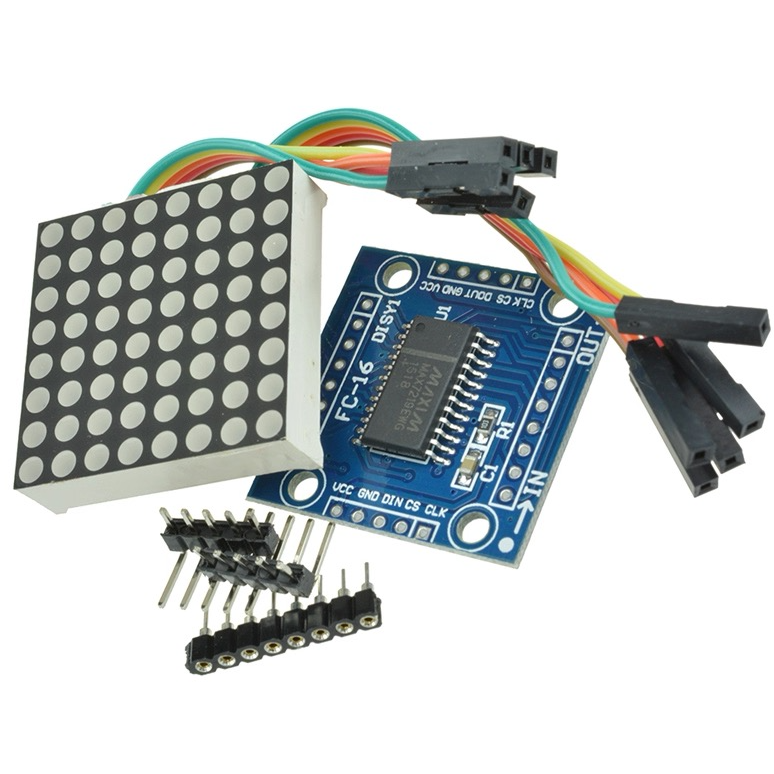
Easy 3-Wire Interface
Only three microcontroller pins are required to control all 64 LEDs.
Built-in Display RAM
Integrated 8×8 RAM stores display data, eliminating the need for constant refreshing by the microcontroller.
Flicker-Free Display
Automatic multiplex scanning provides stable, continuous LED illumination.
Adjustable Brightness
Supports both analog and digital brightness adjustment with up to 16 intensity levels.
BCD Decoder
Built-in Code-B decoder simplifies driving 7-segment displays.
Cascade Support
Multiple modules can be connected together to create longer scrolling displays.
Low Power Shutdown
Consumes approximately 150 μA in shutdown mode.
Scan Limit Register
Allows displaying from 1 to 8 digits, reducing unnecessary power consumption.
Display Test Mode
Turns on every LED simultaneously for testing purposes.
Wide Microcontroller Compatibility
Works with:
· Arduino
· ESP8266
· ESP32
· STM32
· Raspberry Pi
· PIC
· AVR
· 8051
· MSP430
MAX 7219 Applications
The MAX 7219 is suitable for a wide variety of electronic display projects.
LED Message Boards
Create scrolling text displays for information boards or advertising signs.
Digital Clocks
Drive multiple 7-segment displays for clock and timer projects.
Scoreboards
Ideal for sports score displays and competition timers.
Sensor Data Displays
Show temperature, humidity, voltage, or other sensor readings.
Industrial Control Panels
Display operating status and production information.
Animation Projects
Create animated icons and LED effects using the 8×8 matrix.
Educational Projects
Commonly used in electronics learning and embedded system development.
DIY Electronics
Perfect for hobby projects involving Arduino, Raspberry Pi, and ESP32.
MAX7219 Alternative
Can use several display modules as alternatives to the MAX 7219, depending on your project's display requirements, interface, and budget.
16×2 LCD 1602A
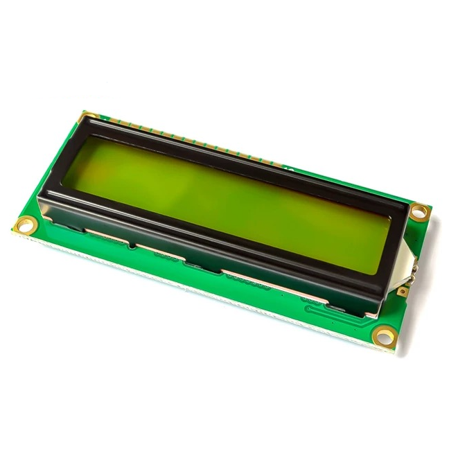
The 16×2 LCD is one of the most popular character displays for embedded projects. It can display up to 32 ASCII characters across two lines, making it ideal for showing sensor readings, menus, and system status information. It supports both a standard parallel interface and an optional I2C interface, making it easy to integrate with Arduino, Raspberry Pi, and other microcontrollers.
TM1637 4-Digit Display Module
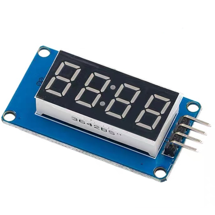
The TM1637 4-digit display module features a 0.36-inch 4-digit common-anode LED display with a built-in TM1637 driver IC. It communicates with a microcontroller using only two signal wires, reducing the number of required I/O pins. The module offers 8 adjustable brightness levels, supports both 3.3V and 5V logic levels, and includes four M2 mounting holes for easy installation. Commonly used in digital clocks, countdown timers, counters, and voltage displays.
2.4-inch TFT Display
The 2.4-inch TFT display is a full-color graphical display that supports images, icons, animations, and graphical user interfaces. Unlike the MAX 7219, which is designed for LED matrices and numeric displays, a TFT display provides much richer visual output, making it suitable for smart home devices, IoT dashboards, portable instruments, and touchscreen applications.
128×64 Graphic LCD
The 128×64 Graphic LCD is a monochrome display capable of showing both text and graphics. It supports custom fonts, symbols, charts, and simple animations, making it an excellent choice for industrial equipment, measurement instruments, embedded systems, and control panels. Compared with a color TFT display, it offers lower power consumption while still providing greater flexibility than a standard character LCD.
How to Program MAX7219 8x8 Display Driver IC?
Programming the MAX 7219 typically involves sending 16-bit commands over its serial interface.
The general programming process is:
1. Initialize the MAX7219 registers.
2. Set the scan limit.
3. Configure decode mode if using 7-segment displays.
4. Set display brightness.
5. Disable shutdown mode.
6. Write data into the display RAM.
7. Refresh only the digits that need updating.
For Arduino, popular libraries such as LedControl or MD_Parola greatly simplify this process, allowing you to display scrolling text, animations, and custom graphics with only a few lines of code.
Connecting Multiple Display Modules
The MAX 7219 LED matrix module supports cascading, allowing multiple modules to be connected together to create larger displays such as scrolling text boards, digital signs, and extended LED animations. By using the cascade function, can control several MAX 7219 modules by a single microcontroller with only three communication pins.
Each MAX 7219 module has an input port and an output port. The input port is connected to the microcontroller, while the output port is used to connect the next display module.
For a single MAX7219 module, connect:
· VCC → 5V power supply
· GND → Ground
· DIN → Microcontroller data pin
· CS → Chip select pin
· CLK → Clock pin
When connecting multiple modules:
1. Connect the DIN pin of the first MAX7219 module to the microcontroller.
2. Connect the DOUT pin of the first module to the DIN pin of the second module.
3. Continue connecting the DOUT pin of each module to the DIN pin of the next module.
4. Connect all VCC, GND, CLK, and CS pins together.
The data sent from the microcontroller is shifted through each MAX 7219 module in the chain. Each module receives its assigned display data while passing the remaining data to the next module.
Example Connection with 8051 Microcontroller
For an 8051 system, the wiring can be:
· VCC → 5V
· GND → GND
· DIN → P2.0
· CS → P2.1
· CLK → P2.2
In a multi-module setup:
8051 → MAX7219 Module 1 → MAX7219 Module 2 → MAX7219 Module 3 → ...
The first module receives data directly from the MCU, and each additional module is connected through the previous module's output interface.
This cascading feature makes the MAX 7219 an excellent choice for building large LED displays while minimizing hardware complexity and saving valuable microcontroller GPIO resources.
MAX7219 PDF Datasheet
For complete electrical characteristics, timing diagrams, register descriptions, programming information, and application circuits, you can check the data sheet PDF provided by the manufacturer.
Frequently Asked Questions [FAQ]
What is the MAX7219 module?
The MAX 7219 module is a serial LED display driver that controls an 8×8 LED matrix, eight 7-segment displays, or 64 individual LEDs using only three microcontroller pins. It integrates multiplexing, brightness control, display RAM, and scanning circuitry for simple, flicker-free operation.
What is the difference between MAX7219CNG and MAX7219ENG?
Both devices provide the same display-driving functions and electrical performance. The primary differences are package type, operating temperature range, and product grade. Designers typically choose the version that best matches their environmental requirements and manufacturing preferences.
Is MAX7219 compatible with Arduino?
Yes. The MAX7219 is fully compatible with Arduino boards, including the Uno, Nano, Mega, and Pro Mini. Popular libraries such as LedControl, MD_MAX72XX, and MD_Parola make it easy to display text, animations, numbers, and custom graphics.
How do you connect multiple MAX7219?
Multiple MAX7219 modules are connected in series by linking the DOUT pin of one module to the DIN pin of the next. The VCC, GND, CLK, and CS lines are shared among all modules, allowing a single microcontroller to control large displays.
What is the segment current of a MAX7219?
The segment current is programmable through a single external resistor connected to the ISET pin. Depending on the resistor value, the MAX 7219 can typically supply up to approximately 40 mA per segment while maintaining consistent LED brightness.
How do you cascade MAX7219?
To cascade MAX 7219 devices, connect the first module to the microcontroller, then connect each module's DOUT pin to the next module's DIN pin. Data shifts through the chain, allowing multiple LED matrices or displays to operate as one continuous display.
Conclusion
The MAX7219 LED display driver module is a simple, efficient, and versatile solution for controlling LED matrices, 7-segment displays, and individual LEDs. With its built-in multiplexing, display RAM, brightness adjustment, and serial communication interface, it greatly reduces the workload of the microcontroller while providing a stable, flicker-free display. Requiring only three GPIO pins and supporting cascade connections, multiple MAX 7219 modules can be combined to create larger scrolling displays and complex LED projects. Its compatibility with Arduino, ESP32, Raspberry Pi, 8051, and other microcontrollers makes it a popular choice for hobbyists, students, and embedded system developers. For applications requiring easy LED control, compact design, and flexible expansion, the MAX 7219 remains one of the most practical display driver solutions available.
Read More:
1. SX1276 LoRa Transceiver: Pinout and Wireless Lora Module
2. PIC12F675 Microcontroller: Pinout and Development Board
3. Mini MP1584 DC-DC 3A Buck Converter Module: Complete Guide
HOT NEWS
TP4056 Charging Module Pinout, Working, and Applications
TP4056 Charging Module Pinout, Working, and Applications
2026-01-23
LR41 Battery Guide: Specifications, Equivalents, and Uses
LR41 Battery Specifications, Equivalents, and Uses
2025-12-14
Understanding A 0603 Resistor
0603 resistor,dimensions,marking code, values
2025-05-29
Understanding The CD4051 Analog Multiplexer
CD4051 analog multiplexer
2025-06-30
MT3608 Boost Converter - An In-Depth Guide
MT3608 Boost Converter
2025-09-04
Complete Guide to the 220 Ohm Resistor
220 Ohm Resistor
2025-07-28
The 0402 Resistor: A Comprehensive Guide
0402 Resistor
2025-05-06
Guide To The XL6009 Boost Converter
XL6009 Boost Converter
2025-09-05
Mini MP1584 DC-DC 3A Buck Converter Module: Complete Guide
Mini MP1584 DC-DC 3A Buck Converter Module: Complete Guide
2026-03-26
What Is A 1206 Resistor?
1206 resistor dimensions,footprint,value
2025-06-05