




 BOM
BOM Cart
Cart Product Catalog
LCD1602 Display Module 1602A 16X2 Compatible with Arduino R3 Mega2560 Raspberry Pi
2026-08-01
The LCD1602 module is one of the most widely used character LCD displays in embedded electronics. Thanks to its low cost, easy interface, and reliable performance, it is commonly found in Arduino, Raspberry Pi, ESP32, STM32, AVR, and PIC projects.
Unlike graphic LCDs, the LCD 1602 design specifically for displaying letters, numbers, punctuation marks, and custom characters. It provides a simple way to display sensor readings, menu systems, device status, clocks, temperatures, and other information without requiring significant processing power.
In this guide, you'll learn everything about the LCD 1602A module, including its specifications, pinout, features, Arduino wiring, I2C interface, applications, and frequently asked questions.
1. What is the LCD1602 Display Module?
2. LCD 1602 Technical Specifications
4. 1602 LCD Display Key Features
5. 1602A LCD Module Applications
6. LCD 1602 Arduino Code and Wiring
8. Frequently Asked Questions [FAQ]
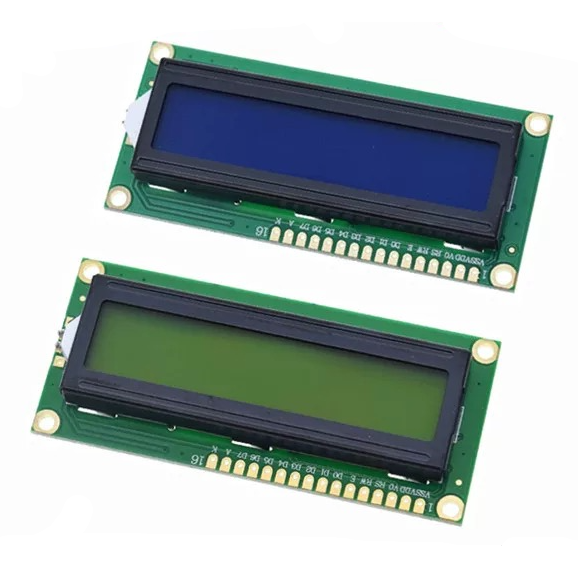
What is the LCD1602 Display Module?
The LCD1602 (LCD1602A) is a popular character LCD designed to display letters, numbers, symbols, and custom characters. It features a 16×2 character display with a 5×7 dot matrix for each character and supports both 4-bit and 8-bit parallel communication, making it compatible with a wide range of microcontrollers.
The module includes DDRAM for display data, CGROM for built-in character fonts, and CGRAM, which allows users to create and store up to eight custom 5×8 characters. It also provides various built-in commands, such as clearing the display, controlling the cursor, enabling blinking, and shifting the display.
An internal power-on reset circuit automatically initializes the module when the supply voltage exceeds 4.5V, ensuring reliable startup. With its low power consumption, stable performance, and easy interfacing, the LCD 1602 widely use in Arduino, ESP32, Raspberry Pi, industrial controllers, measurement instruments, and other embedded electronics projects.
LCD 1602 Technical Specifications
The LCD1602A is designed for stable operation in a wide range of embedded applications. It operates from a 4.8V to 5.2V logic supply and supports both 4-bit and 8-bit parallel communication. The module is available in several display color combinations, including blue with white characters, yellow-green with black characters, and gray with black characters, allowing users to choose the best option for their application.
Parameter | Specification |
Display Type | Character LCD |
Display Format | 16 × 2 Characters |
Character Size | 5 × 7 Dot Matrix |
Logic Supply Voltage | 4.8V–5.2V |
LCD Drive Voltage | (VDD−VO) +5V or +3V |
Interface | 4-bit or 8-bit Parallel |
Display Colors | White on Blue, Black on Yellow-green Or Black on Gray Background |
Operating Temperature | -20°C to +70°C |
Storage Temperature | -30°C to +80°C |
Logic Current | 1.7mA (Max, without backlight) |
Backlight Current | 24mA (Max) |
Character Generator RAM | 8 Custom Characters |
Character Generator ROM | Built-in ASCII Character Set |
LCD1602 Pinout
The 1602A uses a standard 16-pin interface for power, control, data communication, and backlight connections. It supports both 4-bit and 8-bit parallel communication modes. In 4-bit mode, only require pins D4–D7, reducing the number of microcontroller I/O pins. Pins RS, RW, and E control data and command transmission, while use VO to adjust the display contrast with a potentiometer.
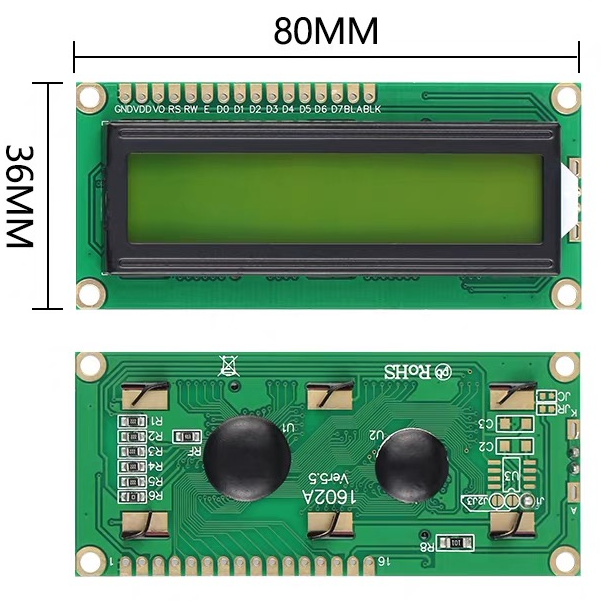
Pin | Symbol | I/O | Description |
1 | VSS | Power | Ground (0V) |
2 | VDD | Power | +5V Power Supply |
3 | VO | Input | LCD Contrast Voltage Input |
4 | RS | Input | Register Select (Command/Data Selection) |
5 | RW | Input | Read/Write Control Signal |
6 | E | Input | Enable Signal |
7 | D0 | I/O | Data Bit 0 |
8 | D1 | I/O | Data Bit 1 |
9 | D2 | I/O | Data Bit 2 |
10 | D3 | I/O | Data Bit 3 |
11 | D4 | I/O | Data Bit 4 |
12 | D5 | I/O | Data Bit 5 |
13 | D6 | I/O | Data Bit 6 |
14 | D7 | I/O | Data Bit 7 |
15 | BLA | Power | LED Backlight Anode (+5V) |
16 | BLK | Power | LED Backlight Cathode (0V/GND) |
LCD1602 Pin Description
VSS
Ground connection for the module.
VDD
Provides the +5V power supply.
VO
Adjusts LCD contrast using a potentiometer.
RS
Determines whether incoming data is interpreted as commands or display characters.
RW
Selects read or write mode. Most Arduino projects permanently connect RW to ground for write-only operation.
E
Enable signal used to latch data into the LCD controller.
D0–D7
Eight-bit data bus. When operating in 4-bit mode, only use D4–D7.
BLA and BLK
Power pins for the LED backlight.
LCD1602A Block Diagram
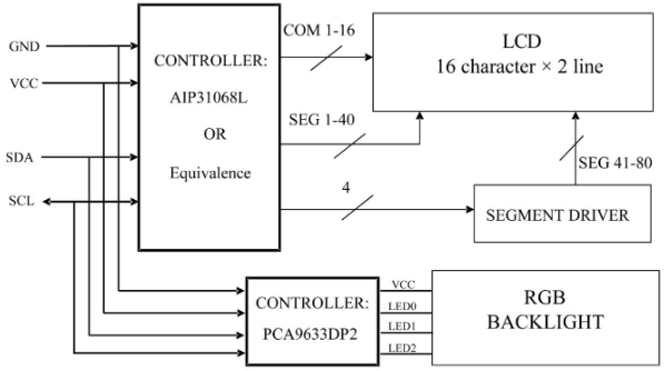
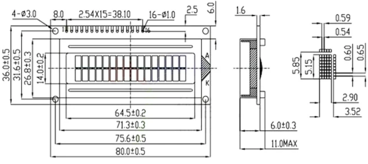
LCD1602A Size/Dimension
1602 LCD Display Key Features
The LCD1602 remains one of the most popular character displays because it combines simplicity with excellent reliability.
16×2 Character Display
Displays up to 32 ASCII characters across two lines.
5×7 Character Font
Each character uses a clear and readable 5×7 pixel matrix.
4-Bit and 8-Bit Communication
Supports both communication modes, allowing users to save GPIO pins by choosing the 4-bit interface.
Wide Operating Temperature
Designed for industrial applications with an operating range of −20°C to +70°C.
Multiple Display Colors
Available in several color combinations:
· Blue background with white text
· Yellow-green background with black text
· Gray background with black text
Custom Character Generator
Supports 8 programmable characters stored inside CGRAM.
Automatic Power-On Initialization
An internal reset circuit automatically configures the display after power-up.
Low Power Consumption
Consumes only 1.7mA without the backlight, making it suitable for battery-powered devices.
COB Manufacturing Process
Uses Chip-On-Board (COB) technology for improved durability and stable performance.
Optional 3.3V or 5V Versions
Some modules include a negative-voltage circuit for 3.3V operation, while standard versions operate directly from 5V.
I2C Expansion Support
LCD 1602 modules can include the PCF8574 I2C I/O expander, reducing the required interface to only two signal wires:
· SDA
· SCL
The PCF8574 offers:
· 8-bit quasi-bidirectional I/O
· Low power consumption
· Strong LED drive capability
· Interrupt output (INT)
· Simple MCU expansion through the I2C bus
1602A LCD Module Applications
The LCD1602 is suitable for numerous embedded and industrial applications, including:
· Arduino learning projects
· Temperature monitoring systems
· Digital clocks
· Electronic weighing scales
· Home automation systems
· Smart agriculture
· Industrial control panels
· Medical instruments
· Security systems
· Laboratory equipment
· Power supply displays
· Data logging devices
· Battery monitoring systems
· Robotics
· IoT prototypes
LCD 1602 Arduino Code and Wiring
Wiring Diagram
LCD1602 | Arduino Uno |
VSS | GND |
VDD | 5V |
VO | Potentiometer |
RS | D12 |
RW | GND |
E | D11 |
D4 | D5 |
D5 | D4 |
D6 | D3 |
D7 | D2 |
A | 5V |
K | GND |
Arduino Example
#include <LiquidCrystal.h>
LiquidCrystal lcd(12, 11, 5, 4, 3, 2);
void setup()
{
lcd.begin(16,2);
lcd.print("Hello World!");
}
void loop()
{
}
This program initializes the display and prints "Hello World!" on the first line.
LCD 1602 with I2C IIC
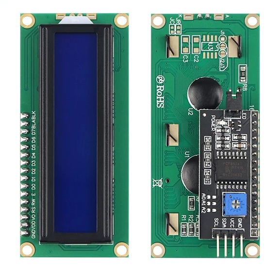
The LCD1602 I2C Module is an improved version of the standard 1602A display that uses the PCF8574 I/O expansion chip to simplify communication with microcontrollers. By using the I2C bus, the module allows most MCUs to expand remote I/O ports with only two communication lines: SDA (data) and SCL (clock).
The PCF8574 contains an 8-bit quasi-bidirectional I/O port and an integrated I2C interface. It features low power consumption and strong output drive capability, allowing it to directly control devices such as LEDs. The module also provides an INT interrupt output, which can connect to the MCU interrupt system. Through this interrupt signal, the remote I/O port can notify the MCU when new input data is available without requiring continuous I2C communication.
Compared with the traditional parallel LCD1602 interface, the I2C version greatly reduces wiring complexity and saves valuable GPIO pins, making it ideal for Arduino, ESP32, Raspberry Pi, and other embedded projects.
LCD1602 I2C Module Specifications
Parameter | Description |
Controller Chip | PCF8574 I/O Expander |
Communication Interface | I2C Protocol |
Operating Voltage | 2.5V–6V |
Module Size | 41mm × 19mm × 15.3mm |
Default I2C Address | 0x27 |
Backlight Control | Jumper selectable |
Contrast Adjustment | Adjustable potentiometer |
Cascade Support | Up to 8 modules |
LCD1602 I2C Pin Definition
The I2C module uses four main pins for connection:
Pin | Description |
GND | System power ground |
VCC | Positive power supply |
SDA | I2C data line |
SCL | I2C clock line |
The pin header on the right side of the I2C adapter corresponds to the first pin of the LCD1602 display.
I2C Address Configuration
The LCD1602 I2C module supports connecting multiple displays on the same I2C bus. Up to 8 modules can be cascaded by changing the device address through the A0, A1, and A2 solder pads.
The default address is 0x27, with all A0/A1/A2 pads left open. The address can be modified by changing the solder pad configuration:
· Solder pad open = Logic 1
· Solder pad shorted = Logic 0
This feature allows multiple LCD1602 displays to work together without address conflicts.
Backlight and Contrast Adjustment
The module includes an LED backlight that can be controlled through a jumper cap:
· Jumper installed: Backlight enabled
· Jumper removed: Backlight disabled
A built-in blue potentiometer is provided for contrast adjustment. Rotating the potentiometer clockwise increases contrast, while rotating it counterclockwise decreases contrast, allowing users to easily adjust the display clarity.
Frequently Asked Questions [FAQ]
What is the function of LCD 1602?
The LCD1602 is a 16×2 character liquid crystal display used to show letters, numbers, symbols, and custom characters. Commonly use in embedded systems to display menus, sensor readings, system status, temperatures, clocks, and user interface information with low power consumption.
How to wire an LCD1602?
Connect VSS to GND, VDD to 5V, VO to a potentiometer for contrast adjustment, RS and E to digital control pins, RW to GND, D4–D7 to Arduino digital pins for 4-bit mode, and connect the backlight pins to 5V and GND.
How to connect LCD 16 * 2 to Arduino?
Connect the LCD1602 using either the standard 4-bit parallel interface or an I2C backpack. The parallel method requires six Arduino GPIO pins, while the I2C version only needs SDA and SCL, simplifying wiring and leaving more pins available for other devices.
What is the contrast pin for LCD1602?
The VO pin controls the display contrast. Usually connect to the center terminal of a 10kΩ potentiometer, allowing users to adjust character visibility by varying the voltage between ground and the supply voltage.
What is the operating voltage of LCD1602?
The LCD1602 logic supply voltage typically ranges from 4.8V to 5.2V, with standard modules designed for 5V operation. Some versions include additional circuitry that enables reliable operation with a 3.3V power supply.
How to use LCD 1602 with ESP32?
To use an LCD1602 with an ESP32, recommend an I2C backpack because it requires only the SDA and SCL pins. Install the LiquidCrystal_I2C library, connect the module, configure the correct I2C address, and initialize the display in your program.
What is an LCD1602 module with pin header?
An LCD1602 module with a pin header includes a pre-soldered 16-pin connector, making it easy to plug into a breadboard, jumper wires, or development board without additional soldering, simplifying prototyping and circuit assembly.
How to connect LCD1602 to breadboard?
Insert the LCD1602 into the breadboard or connect it using header pins and jumper wires. Supply 5V power, connect ground, adjust the contrast with a potentiometer, and wire either the parallel interface or an I2C backpack to your microcontroller.
Can I use an LCD without an I2C?
Yes. The LCD1602 was originally designed with a standard 4-bit or 8-bit parallel interface and operates perfectly without an I2C module. An I2C backpack is simply an optional adapter that reduces wiring complexity and conserves microcontroller GPIO pins.
Conclusion
The LCD1602 display module remains one of the best choices for displaying text in embedded systems. Its straightforward interface, dependable performance, low power consumption, and compatibility with popular development platforms make it suitable for beginners and professionals alike. Whether you use the standard parallel interface or an I2C backpack, the LCD1602 offers a cost-effective and reliable solution for displaying characters, numbers, and custom symbols in countless electronic projects.
Read More:
1. CC1101 Wireless RF Transceiver Module Board Guide
2. Mini MP1584 DC-DC 3A Buck Converter Module: Complete Guide
HOT NEWS
TP4056 Charging Module Pinout, Working, and Applications
TP4056 Charging Module Pinout, Working, and Applications
2026-01-23
LR41 Battery Guide: Specifications, Equivalents, and Uses
LR41 Battery Specifications, Equivalents, and Uses
2025-12-14
Understanding A 0603 Resistor
0603 resistor,dimensions,marking code, values
2025-05-29
MT3608 Boost Converter - An In-Depth Guide
MT3608 Boost Converter
2025-09-04
The 0402 Resistor: A Comprehensive Guide
0402 Resistor
2025-05-06
Complete Guide to the 220 Ohm Resistor
220 Ohm Resistor
2025-07-28
What Is A 1206 Resistor?
1206 resistor dimensions,footprint,value
2025-06-05
Guide To The XL6009 Boost Converter
XL6009 Boost Converter
2025-09-05
Understanding The CD4051 Analog Multiplexer
CD4051 analog multiplexer
2025-06-30
120 Ohm Resistor- Specifications, Applications, and Features
2025-05-12