




 BOM
 Cart
 Product Catalog
The AS5600 is a 12-bit magnetic rotary position sensor designed for accurate, contactless angle measurement. It uses Hall-effect technology to detect the direction of a magnetic field and converts the measured position into digital or analog output. With I²C communication, PWM output, and a configurable angular range, this sensor is suitable for Arduino, ESP32, STM32, robotics, motor control, and electronic knob applications.
This guide explains how the AS5600 works, its pinout and specifications, how to connect it to popular microcontrollers, and how it compares with the AS5048A and AS5600L. It also covers magnetic encoder modules, practical installation considerations, and frequently asked questions.
5. Interfacing the AS5600 with Arduino — Wiring and Code
7. AS5600 vs AS5048A vs AS5600L
8. AS5600 Magnetic Encoder High Precision Sensor Module
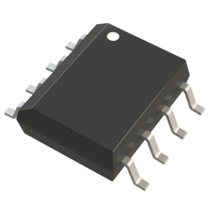
What Is the AS5600?
The AS5600 is a contactless magnetic rotary position sensor developed by ams OSRAM. It measures angular position using planar Hall sensors that detect the magnetic field component perpendicular to the surface of the chip. Unlike a conventional mechanical potentiometer, it does not require electrical contacts to move across a resistive track, reducing mechanical wear and helping maintain long-term reliability.
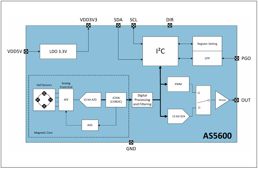
The sensor processes the magnetic field through an internal signal-conditioning circuit. Amplify and filter signals from the Hall sensors before an analog-to-digital converter (ADC) digitizes them. A built-in CORDIC (Coordinate Rotation Digital Computer) block then calculates the magnetic field angle and magnitude. Automatic gain control (AGC) adjusts the amplification according to the field strength to help compensate for variations in temperature and magnetic field intensity.
The device provides a 12-bit angular measurement, representing one complete revolution with 4096 digital positions. Its default measuring range is 0° to 360°, but can program the start and stop positions to map the full output resolution to a smaller angular range.
The output stage supports analog voltage and PWM signals, while an I²C interface allows a microcontroller to read the angle and configure the sensor's non-volatile memory. This flexibility makes the AS 5600 suitable for contactless potentiometers, rotary knobs, pedals, robotic joints, and other applications requiring absolute angular position measurement.
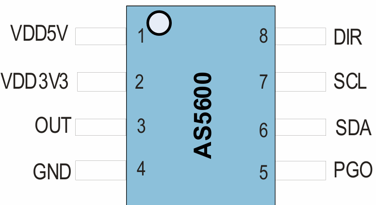
AS5600 Pinout
The AS 5600 is available in an 8-pin SOIC package. Its pins provide power, ground, analog or PWM output, I²C communication, programming options, and direction control.
|
Pin No |
Name |
Description |
|
1 |
VDD5V |
Supply input for 5 V operation; requires appropriate decoupling |
|
2 |
VDD3V3 |
3.3 V supply input; check the datasheet for supply and capacitor requirements |
|
3 |
OUT |
Analog voltage or PWM output |
|
4 |
GND |
Ground connection |
|
5 |
PGO |
Programming option input; internal pull-up |
|
6 |
SDA |
I²C serial data; Require external pull-up |
|
7 |
SCL |
I²C serial clock; Require external pull-up |
|
8 |
DIR |
Rotation direction control |
Pinout notes:
VDD5V and VDD3V3: Use the appropriate supply configuration for the chip or breakout board. Do not assume both supply pins should connect directly to the same voltage.
OUT: Select analog or PWM operation according to the required interface and configuration.
SDA and SCL: Connect these pins to the microcontroller's I²C bus. Require suitable pull-up resistors unless already provided by the module.
DIR: Connect to GND for increasing angle values in the clockwise direction, or to the supply as specified in the datasheet for counterclockwise operation.
PGO: This pin controls a programming option and should connect according to the recommended circuit for the selected operating mode.
For a breakout board, check its schematic because onboard regulators, capacitors, and pull-up resistors can change the recommended wiring.
Functional Block Diagram
AS5600 Specifications
The following table summarizes the main specifications of the AS 5600 magnetic angle sensor. Values for the bare IC and breakout modules may differ, particularly for supply connections and current consumption.
|
Parameter |
Value |
|
Manufacturer |
ams OSRAM AG |
|
Sensing technology |
Hall effect |
|
Measurement type |
Angular position |
|
Electrical rotation range |
0°~360° |
|
Resolution |
12-bit, 4096 positions per revolution |
|
Supply voltage |
3.3 V or 5 V, depending on configuration |
|
Output options |
Analog voltage, PWM, I²C |
|
I²C address |
0x36 |
|
Actuator |
External magnet, not included with the IC |
|
Mounting type |
Surface mount |
|
Package |
8-SOIC |
|
Operating temperature |
-40°C~125°C |
|
Programmable angle range |
Up to 360°, with smaller ranges configurable |
|
Direction control |
DIR input |
|
Typical module size |
Depends on the breakout board |
The 12-bit resolution corresponds to approximately 0.0879° per digital step across a full revolution. This is the nominal angular resolution, not a guarantee of absolute measurement accuracy. Actual performance depends on magnet alignment, air gap, magnetic field strength, mechanical tolerances, and the sensor's specifications.
How to Use the AS5600?
The sensor measures rotation by sensing a magnetic field rather than relying on a mechanical shaft contact. To use it, position a suitable diametrically magnetized magnet above the sensing chip, connect the power and output interface, and read the measured angle with a microcontroller.
Magnet Installation
Magnet placement is one of the most important factors affecting measurement quality. The sensor is generally used with a diametrically magnetized, two-pole magnet whose north and south poles are arranged across its diameter. The magnet should be centered over the sensing area, with its magnetization direction and distance following the datasheet recommendations.
An off-center magnet, excessive air gap, unsuitable magnet, or weak magnetic field can cause angle errors or unreliable readings. Check the device's magnetic field status information when troubleshooting.
Choose an Output Interface
The sensor offers three practical ways to obtain angle information.
|
Interface |
How It Works |
Typical Use |
|
I²C |
The microcontroller reads angle registers digitally |
Arduino, ESP32, STM32 |
|
PWM |
Angle is represented by pulse width |
Controllers with timer inputs |
|
Analog |
Angle is represented by an output voltage |
ADC inputs and analog control systems |
I²C is a convenient choice when the application needs a numerical angle value. PWM can be useful when the controller already has timer input capture, while analog output works well with systems that measure voltage using an ADC.
Read the Angle
For I²C operation, the AS 5600 uses the fixed 7-bit address 0x36. The raw angle register begins at 0x0C, and the raw angle is represented by 12 bits across two bytes.
After reading the register, combine the two bytes, retain the 12-bit value, and convert it into degrees. Can use the resulting angle for position feedback, user-interface controls, rotary input, or motor-position monitoring.
Configure the Angular Range
The default configuration measures a complete 360° rotation. Using the I²C interface, can program the start and stop positions so that the available output resolution is distributed over a smaller rotation range.
For example, a rotary control with a limited mechanical travel may use a configured range rather than the entire revolution. Confirm the required programming procedure and register settings in the datasheet before changing the non-volatile configuration.
Interfacing the AS5600 with Arduino — Wiring and Code
The AS 5600 can connect to an Arduino Uno, ESP32, or STM32 through I²C. The following examples demonstrate how to read the raw angle and convert it into degrees.
AS5600 Wiring
The following connections use common default I²C pins. Confirm the actual pin mapping for your board and the supply requirements of your particular module.
|
AS5600 Module Pin |
Arduino Uno |
ESP32 |
STM32 (I²C1 example) |
|
VCC |
5 V or 3.3 V, as supported by module |
3.3 V |
3.3 V |
|
GND |
GND |
GND |
GND |
|
SCL |
A5 |
GPIO 22 |
PB6 |
|
SDA |
A4 |
GPIO 21 |
PB7 |
|
DIR |
GND |
GND |
GND |
Wiring precautions: The ESP32 and many STM32 boards use 3.3 V logic. Ensure that SDA and SCL pull-ups do not raise the bus above the microcontroller's permitted input voltage. If using a bare AS 5600 IC rather than a breakout board, follow the manufacturer's supply and decoupling circuit.
Arduino Uno Example
This example reads the two raw-angle registers through the Arduino Wire library and prints the result to the Serial Monitor.
#include <Wire.h>
const uint8_t AS5600_ADDRESS = 0x36;
const uint8_t RAW_ANGLE_REG = 0x0C;
void setup() {
Serial.begin(115200);
Wire.begin();
}
void loop() {
Wire.beginTransmission(AS5600_ADDRESS);
Wire.write(RAW_ANGLE_REG);
if (Wire.endTransmission(false) == 0) {
uint8_t count = Wire.requestFrom(
AS5600_ADDRESS, (uint8_t)2
);
if (count == 2) {
uint16_t highByte = Wire.read();
uint16_t lowByte = Wire.read();
uint16_t rawAngle =
((highByte << 8) | lowByte) & 0x0FFF;
float degrees = rawAngle * 360.0 / 4096.0;
Serial.print("Raw Value: ");
Serial.print(rawAngle);
Serial.print("tAngle: ");
Serial.print(degrees, 2);
Serial.println(" degrees");
}
}
delay(100);
}
How it works:
The program initializes I²C communication and selects register 0x0C. It then requests two bytes from the sensor, combines them into a 16-bit value, and masks the result to retain the 12-bit angle data. Finally, the program converts the raw value to degrees and prints it to the Serial Monitor.
Open the Serial Monitor at 115200 baud to observe the readings as the magnet rotates.
ESP32 Example
The ESP32 supports configurable I²C pins, allowing the sensor to connect through GPIO 21 for SDA and GPIO 22 for SCL in this example.
#include <Wire.h>
#define I2C_SDA 21
#define I2C_SCL 22
const uint8_t AS5600_ADDRESS = 0x36;
const uint8_t RAW_ANGLE_REG = 0x0C;
void setup() {
Serial.begin(115200);
Wire.begin(I2C_SDA, I2C_SCL, 400000);
}
void loop() {
Wire.beginTransmission(AS5600_ADDRESS);
Wire.write(RAW_ANGLE_REG);
if (Wire.endTransmission(false) == 0) {
if (Wire.requestFrom(
AS5600_ADDRESS, (uint8_t)2) == 2) {
uint16_t highByte = Wire.read();
uint16_t lowByte = Wire.read();
uint16_t rawAngle =
((highByte << 8) | lowByte) & 0x0FFF;
float degrees = rawAngle * 360.0 / 4096.0;
Serial.printf(
"ESP32 Read -> Angle: %.2f degreesn",
degrees
);
}
}
delay(50);
}
This example configures the I²C bus to 400 kHz. Use a lower clock speed if the wiring, pull-up resistors, or connected devices do not support reliable communication at that rate.
STM32 Example Using HAL
For STM32 projects configured with STM32CubeMX, the HAL I²C functions can read the angle register. This example assumes that hi2c1 has already been initialized and PB6/PB7 are configured for the selected I²C1 instance.
#define AS5600_ADDR (0x36 << 1)
#define RAW_ANGLE_REG 0x0C
uint8_t buf[2];
uint16_t raw_angle;
float degrees;
while (1) {
if (HAL_I2C_Mem_Read(
&hi2c1,
AS5600_ADDR,
RAW_ANGLE_REG,
I2C_MEMADD_SIZE_8BIT,
buf,
2,
100) == HAL_OK) {
raw_angle =
(((uint16_t)buf[0] << 8) | buf[1])
& 0x0FFF;
degrees = (raw_angle * 360.0f) / 4096.0f;
// Use degrees for position feedback
// or transmit it through a serial interface.
}
HAL_Delay(50);
}
In STM32 HAL, the I²C device address is conventionally passed in its 8-bit shifted form, so 0x36 << 1 is used. The code masks the combined register value to 12 bits before calculating the angle.
AS5600 Magnetic Encoders Application
The AS 5600 is suitable for applications that require contactless angular position sensing, long service life, and convenient integration with microcontrollers. Its digital and analog output options make it useful in both embedded control systems and consumer electronics.
Contactless Potentiometers and Rotary Knobs
The sensor can replace a conventional rotary potentiometer in control panels, menu selectors, audio controls, and electronic adjustment knobs. Its non-contact sensing method reduces wear caused by repeated rotation and provides an absolute position reading after power-up.
Robotics and Position Feedback
Robotic joints, small actuators, and rotating mechanisms can use the measured angle as position feedback. A microcontroller can compare the measured position with a target angle and adjust a motor driver accordingly. The sensor measures position; the motor-control algorithm must be implemented separately.
Pedals and User Controls
Contactless angle measurement can be used in pedal mechanisms, joysticks, and other adjustable controls. For safety-critical automotive systems, however, the component's qualification and system-level safety requirements must be evaluated rather than assuming a standard AS5600 is suitable.
RC Servos and Motor Mechanisms
The sensor can measure shaft or linkage position in experimental servo systems and small motorized mechanisms. It can provide feedback for closed-loop control, provided the magnet can be mounted correctly and the controller supports the required sampling and response rate.
Industrial and Embedded Equipment
In equipment requiring repeated angular adjustment, the device can measure rotary controls, position-adjustment mechanisms, and compact electromechanical assemblies. Its I²C interface simplifies integration with embedded processors, while PWM and analog outputs support alternative control architectures.
AS5600 vs AS5048A vs AS5600L
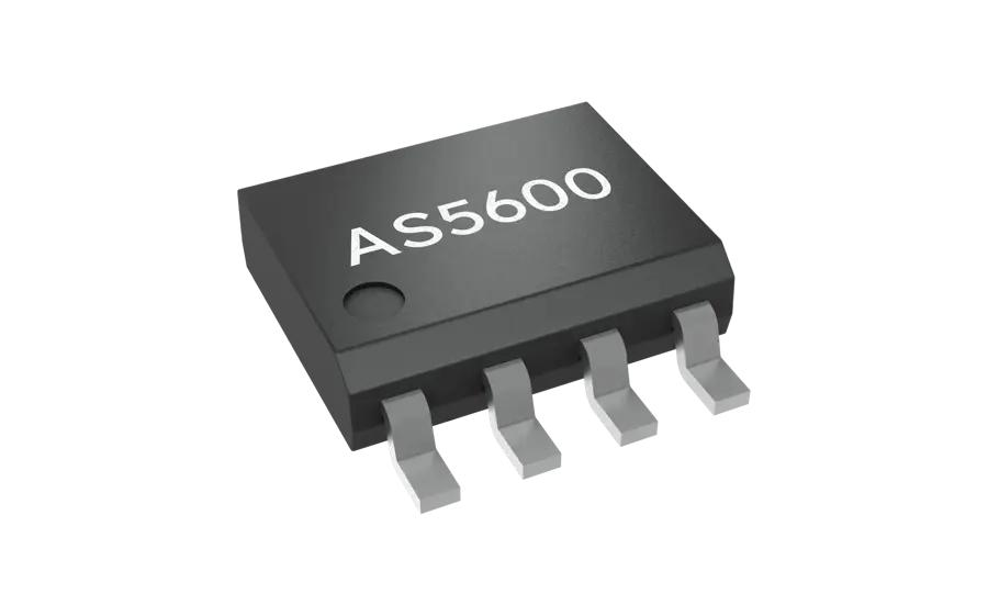
The AS5600, AS5048A, and AS5600L are magnetic angle sensors from ams OSRAM, but they differ in interface options, package, and system integration requirements. The best choice depends on the required resolution, communication protocol, mechanical design, and application constraints.
Specification Comparison
|
Parameter |
AS5600 |
AS5048A |
AS5600L |
|
Manufacturer |
ams OSRAM |
ams OSRAM |
ams OSRAM |
|
Sensing technology |
Hall effect |
Hall effect |
Hall effect |
|
Measurement range |
0°~360° |
0°~360° continuous |
0°~360° continuous |
|
Resolution |
12-bit |
14-bit |
12-bit |
|
Main digital interface |
I²C |
SPI |
I²C |
|
Other output options |
Analog, PWM |
PWM, SPI |
PWM, I²C |
|
Supply voltage |
3.3 V or 5 V, depending on configuration |
3.3 V or 5 V, depending on configuration |
Check the device datasheet |
|
Package |
8-SOIC |
14-TSSOP |
8-pin package; verify ordering details |
|
Actuator |
External magnet |
External magnet |
External magnet |
|
Typical application |
Rotary controls and general position sensing |
Higher-resolution position sensing |
I²C-based angle measurement |
Check the exact device datasheets for supported supply ranges, package variants, output modes, and ordering options before designing a production circuit.
AS5600 vs AS5048A
The AS 5600 provides 12-bit resolution, making it suitable for many rotary controls, embedded projects, and general-purpose position feedback applications. Its I²C interface is easy to use with common microcontrollers, and the analog and PWM outputs provide additional flexibility.
The AS5048A offers 14-bit resolution, equivalent to 16,384 digital positions per revolution, compared with 4096 for the AS 5600. It is a potential choice when need finer digital position granularity and SPI is suitable for the system. Higher resolution does not automatically guarantee better absolute accuracy, so the complete sensor specifications and mechanical arrangement still matter.
AS5600 vs AS5600L
Both devices target contactless magnetic angle measurement, and both are associated with I²C-based integration. However, their detailed register maps, communication behavior, available features, and programming procedures should not be assumed to be interchangeable.
The AS5600 is a common choice for hobby projects and general-purpose rotary encoder modules. The AS5600L may be preferable when its particular interface capabilities or device-specific features better match the application. Before substituting one for the other, check the datasheet, software compatibility, package, and electrical requirements.
Which Magnetic Encoder Should You Choose?
Choose the AS5600 for a straightforward I²C rotary sensor with analog and PWM output options. Consider the AS5048A when its higher resolution and SPI interface better suit the control system. Select the AS5600L when its specific features and interface requirements fit the design.
For all three devices, magnet alignment, air gap, magnetic field strength, and mechanical tolerances remain important factors in real-world performance.
AS5600 Magnetic Encoder High Precision Sensor Module
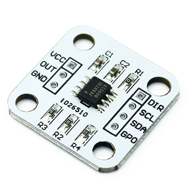
The AS 5600 magnetic encoder module combines the sensor IC with a small printed circuit board and supporting components. Some modules include a voltage regulator, I²C pull-up resistors, and a suitable magnet, making them convenient for prototyping and embedded development.
The sensor uses the Hall effect to detect the orientation of a magnetic field generated by a magnet positioned above the chip. Because it measures rotation without physical contact, it avoids the brush wear and friction associated with many mechanical potentiometers.
Main Features
|
Feature |
Description |
|
Sensing principle |
Contactless Hall-effect magnetic sensing |
|
Resolution |
12-bit, 4096 positions per revolution |
|
Nominal angular step |
Approximately 0.0879° |
|
Measurement range |
0°~360° by default |
|
Programmable range |
Smaller angular ranges can be configured |
|
Interfaces |
I²C, PWM, analog voltage |
|
I²C address |
0x36 |
|
Rotation direction |
Configurable through DIR |
|
Supply |
Depends on the IC configuration and module circuitry |
|
Sensor operating temperature |
-40°C~125°C |
|
Mechanical wear |
No sliding electrical contacts |
Module Power Consumption
The current consumption of an AS5600 module depends on the operating mode, supply voltage, regulator, pull-up resistors, and other onboard circuitry. The bare sensor and a breakout board may therefore have different measured current values.
For battery-powered designs, consult the datasheet's power-mode specifications and measure the complete module under its intended operating conditions. Avoid treating a single typical module current as a guaranteed value for every board.
Magnet Requirements and Installation
The magnet must generate a suitable magnetic field at the sensing element. Generally use a diametrically magnetized magnet, with its north and south poles arranged across the diameter. A typical module may supply with a compatible magnet, but included magnet dimensions and material vary by seller.
The commonly encountered magnet dimensions of around 6 mm in diameter and 2.5 mm in thickness are only an example, not a universal requirement. Select the magnet using the manufacturer's recommended field strength, geometry, and installation distance.
For reliable measurements, center the magnet over the chip and keep its rotational axis aligned with the sensor. If the assembly has excessive runout or the magnet is mounted off-center, the angle reading may exhibit cyclic errors even if the digital output is stable.
Benefits of Using a Breakout Board
A breakout board can simplify prototyping by providing accessible power and communication pins. Some boards also include a regulator and pull-up resistors, reducing the number of external components required.
However, not every module has the same circuit design. Check the actual board schematic before applying 5 V, connecting a 3.3 V microcontroller, or adding external pull-ups. The module's supported input voltage is determined by its complete circuit, not solely by the sensor IC.
Frequently Asked Questions
How does an AS5600 work?
The AS5600 uses Hall-effect sensors to detect the magnetic field generated by a rotating magnet. Its internal circuitry amplifies and digitizes the sensor signals, then calculates the magnetic field angle. The resulting position can be read through I²C or represented by PWM or analog voltage output.
Is AS5600 an absolute encoder?
Yes. The AS 5600 is an absolute magnetic angle sensor. It reports the magnet's angular position within its configured range without requiring incremental pulse counting from a reference point. However, it does not independently identify multiple revolutions, so additional tracking is needed for multi-turn position measurement.
What is the accuracy of the AS5600 encoder?
The AS 5600 provides 12-bit resolution, corresponding to approximately 0.0879° per step over 360°. Resolution is not the same as accuracy. Actual angle error depends on the sensor's specified performance, magnet quality, centering, air gap, stray magnetic fields, and mechanical tolerances.
What is the magnet size of the AS5600 magnetic encoder?
There is no single magnet size for every AS 5600 module. Some breakout boards use magnets approximately 6 mm in diameter and 2.5 mm thick, but the appropriate dimensions depend on magnet material, magnetic strength, and distance from the chip. Follow the sensor manufacturer's magnetic-field recommendations.
What is the angular resolution of the AS5600?
The AS5600 uses a 12-bit output, providing 4096 digital positions across a complete revolution. Dividing 360° by 4096 gives a nominal step of approximately 0.0879°. This describes the spacing between digital values, not the absolute accuracy of the measured mechanical angle.
Can I use multiple AS5600 sensors on the same I2C bus?
Multiple standard AS5600 devices normally share the fixed I²C address 0x36, so they cannot be independently addressed on the same ordinary bus without additional hardware. You can use an I²C multiplexer, separate I²C controllers, or an appropriate bus-switching arrangement to select individual sensors.
What type of magnet does the AS5600 require?
The sensor is designed to measure the direction of a suitable magnetic field, typically produced by a diametrically magnetized two-pole magnet. The magnet should be centered above the chip and installed at a suitable distance. Confirm the recommended field strength and alignment in the datasheet.
What is the difference between AS5600 and AS5600L?
Both sensors are designed for contactless magnetic angle measurement, but their device-specific features, registers, and operating requirements may differ. Do not assume they are direct drop-in replacements. Compare their datasheets and verify I²C compatibility, configuration procedures, supply requirements, and package details before substitution.
Does the AS5600 require calibration after installation?
The AS 5600 does not generally require traditional zero calibration simply to measure a complete rotation. However, correct magnet alignment is essential. For applications with a limited mechanical travel, you may also program the start and stop angles. Mechanical positioning and system-level calibration can still be useful for improving practical accuracy.
What is the magnet size of the AS5600 magnetic encoder?
The required magnet size depends on the module design and the magnetic field at the sensor. A 6 mm × 2.5 mm magnet is common in some small encoder kits, but it is not a universal specification. Verify the magnet's diameter, thickness, material, pole orientation, and recommended air gap before installation.
Conclusion
The AS5600 is a practical solution for contactless rotary position measurement, combining 12-bit angular sensing with I²C, PWM, and analog output options. Its compact package, configurable measurement range, and compatibility with popular microcontrollers make it useful for electronic knobs, robotics, position feedback, and embedded control projects.
To achieve reliable results, choose a suitable magnet, align it carefully with the sensor, use the correct supply and logic levels, and verify the I²C connections. For applications requiring finer digital resolution or a different communication interface, compare the AS5048A and AS5600L against the specific electrical, mechanical, and performance requirements of the design.
Read More:
1. TTP223 Touch Switch - Pinout, Datasheet & Applications
2. Guide to The PIC18F25K20 Microcontroller Chip
3. BC817 Transistor Pinout, Applications, and Equivalents
AS5600 Datasheet:
HOT NEWS
TP4056 Charging Module Pinout, Working, and Applications
TP4056 Charging Module Pinout, Working, and Applications
2026-01-23
LR41 Battery Guide: Specifications, Equivalents, and Uses
LR41 Battery Specifications, Equivalents, and Uses
2025-12-14
Understanding The CD4051 Analog Multiplexer
CD4051 analog multiplexer
2025-06-30
Understanding A 0603 Resistor
0603 resistor,dimensions,marking code, values
2025-05-29
MT3608 Boost Converter - An In-Depth Guide
MT3608 Boost Converter
2025-09-04
The 0402 Resistor: A Comprehensive Guide
0402 Resistor
2025-05-06
Complete Guide to the 220 Ohm Resistor
220 Ohm Resistor
2025-07-28
Mini MP1584 DC-DC 3A Buck Converter Module: Complete Guide
Mini MP1584 DC-DC 3A Buck Converter Module: Complete Guide
2026-03-26
Guide To The XL6009 Boost Converter
XL6009 Boost Converter
2025-09-05
What Is A 1206 Resistor?
1206 resistor dimensions,footprint,value
2025-06-05