




 BOM
 Cart
 Product Catalog
The BT136 is a widely used TRIAC designed for controlling AC power in electronic circuits. It provides bidirectional current switching, allowing it to control both positive and negative half-cycles of an AC waveform. With a 600V off-state voltage rating and a 4A RMS on-state current rating, this component is suitable for general-purpose switching and phase-control applications.
This article introduces the BT136 TRIAC, covering its specifications, package, pinout, CAD models, key features, and practical applications. It also explains how to use this device, discusses equivalent TRIAC components, and compares the BT136 with the BT134 to help you select the right component for your circuit.
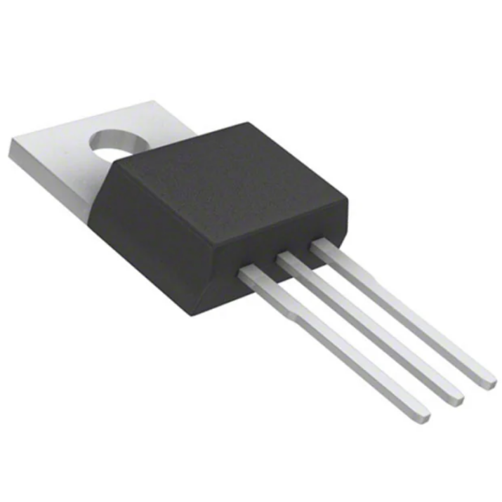
What is BT136 Transistor?
The BT136 is a planar-passivated, four-quadrant TRIAC housed in a SOT78 (TO-220AB) plastic package. It is designed for general-purpose bidirectional switching and phase-control applications in AC circuits.
Unlike a conventional transistor, which typically controls current in one direction, a TRIAC can conduct current in both directions after receiving an appropriate gate trigger signal. This makes it useful for controlling AC loads such as motors, lamps, heaters, and other electrical equipment.
The device supports an off-state voltage of up to 600V and an RMS on-state current of 4A. Its gate trigger voltage is up to 1.5V, while the maximum gate trigger current is 35mA. These characteristics make it suitable for a range of AC switching and power-control circuits.
The four-quadrant triggering capability allows the component to operate with different combinations of main-terminal and gate polarities. Its planar-passivated construction also improves voltage ruggedness, reliability, and resistance to unwanted triggering caused by electrical noise.
BT136 Specifications
The following table summarizes the main electrical and physical specifications of the BT136 TRIAC.
Parameter | Value |
Manufacturer | WeEn Semiconductors |
Packaging | Tube |
TRIAC Type | Standard |
Voltage – Off State | 600V |
On-State RMS Current (IT(RMS)) | 4A |
Gate Trigger Voltage (VGT) | 1.5V (Max) |
Gate Trigger Current (IGT) | 35mA (Max) |
Holding Current (IH) | 15mA (Max) |
Non-Repetitive Surge Current (ITSM) | 25A / 27A |
Configuration | Single |
Operating Temperature | Up to 125°C (TJ) |
Mounting Type | Through Hole |
Package/Case | TO-220-3 |
Supplier Device Package | TO-220AB |
Base Product Number | BT136 |
BT136 Package
The BT136 uses a TO-220AB package with three terminals. This through-hole package is convenient for PCB mounting and provides a metal mounting tab that can be used for heat dissipation.
Its package design makes it suitable for circuits that require moderate power switching. When operating near its maximum current rating, an appropriate heatsink and thermal design may be necessary to keep the junction temperature within the specified limit.
BT136 Pinout and Configurations
Understanding the BT136 pinout is important when connecting the device to an AC switching circuit. It has three terminals: Main Terminal 1 (MT1), Main Terminal 2 (MT2), and Gate (G).
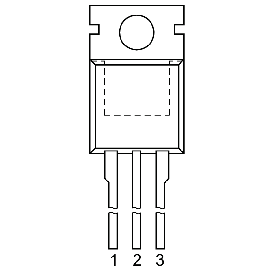
Pin No | Pin Name | Description |
1 | Main Terminal 1 (MT1) | Connected to the AC circuit as one of the main current terminals. |
2 | Main Terminal 2 (MT2) | Connected to the AC circuit as the other main current terminal. |
3 | Gate (G) | Receives the trigger signal to turn on the TRIAC. |
MT1 and MT2 carry the load current, while the gate controls the switching operation. Once triggered, the device continues conducting until the current falls below its holding current, typically around the AC zero-crossing point.
Always check the manufacturer's package drawing and pin configuration before PCB assembly, especially when selecting a replacement component.
BT136 TRIAC Features
The BT 136 offers several features that make it suitable for general-purpose AC power control.
High Blocking Voltage Capability: The device supports an off-state voltage of up to 600V, allowing it to handle relatively high-voltage AC switching applications when operated within its specified limits.
Four-Quadrant Triggering: It can be triggered using different combinations of gate and main-terminal polarities, providing flexibility in AC circuit design.
Improved Noise Immunity: Its less-sensitive gate characteristics help reduce unwanted triggering caused by electrical interference and noise.
Planar-Passivated Construction: The planar-passivated structure improves voltage ruggedness and long-term reliability, supporting stable operation in switching applications.
TO-220AB Package: The through-hole package provides convenient PCB installation and allows additional heatsinking when required.
BT136 Applications
The BT136 is commonly used in general-purpose AC switching and phase-control circuits. Its bidirectional conduction capability allows a single device to control both halves of an AC waveform.
Typical applications include:
General-Purpose Motor Controls: The device can regulate AC motor power using phase-angle control circuits. It is suitable for applications such as small motor speed controllers, provided the motor's current, starting surge, and inductive-load requirements are considered.
General-Purpose Switching: It can switch AC power to resistive and inductive loads in household appliances, electronic equipment, and industrial control circuits.
Light Dimmers: By adjusting the gate triggering point during each AC half-cycle, the TRIAC can control the power delivered to incandescent lamps.
Heater Control: It can regulate the power supplied to resistive heating elements through phase-angle or other suitable switching methods.
AC Power Regulation: The device can be incorporated into AC voltage-control circuits where require bidirectional switching.
TRIAC Application Tips
When designing a circuit with this component, should take several practical considerations into account.
Gate Drive: Select an appropriate gate resistor and trigger circuit to provide sufficient gate current without exceeding the maximum ratings.
Voltage Protection: Consider using an RC snubber or suitable surge protection when switching inductive loads.
Heat Dissipation: Check conduction losses and junction temperature. Use a heatsink when necessary.
Load Compatibility: Consider the starting current, power factor, and inductive characteristics of the connected load.
Electrical Isolation: Use suitable isolation between low-voltage control circuits and mains-voltage circuits.
PCB Design: Maintain appropriate creepage and clearance distances for the operating voltage.
How to use BT136?
Can use the BT 136 as an electronic AC switch by connecting its MT1 and MT2 terminals in series with the load and AC power source. The gate terminal receives a trigger signal from a control circuit to initiate conduction.
A basic AC switching circuit works as follows:
1. Connect the Load: Connect the AC load in series with the TRIAC and the AC supply.
2. Connect the Gate Circuit: Connect the gate to a suitable triggering circuit through an appropriately selected resistor.
3. Apply the Trigger Signal: When sufficient gate current flows, the TRIAC turns on and allows current to pass through the load.
4. Maintain Conduction: After triggering, the device remains on even if remove the gate signal, as long as the main current remains above the holding-current threshold.
5. Turn Off: When the AC current falls below the holding current, the TRIAC turns off. It can then be triggered again during the next half-cycle.
For a light-dimming application, can use a resistor-capacitor timing network to adjust the gate triggering point. Changing the triggering angle changes the portion of each AC half-cycle delivered to the load, thereby controlling its average power.
The gate drive must be designed according to the device's triggering characteristics. The maximum gate trigger current is 35mA, but the actual required current depends on the triggering quadrant and operating conditions.
Important: The BT 136 is designed for AC power switching and connect directly to hazardous mains voltages. Use appropriate isolation, fusing, enclosure protection, and electrical safety practices. Do not connect a low-voltage microcontroller directly to the gate without a properly designed interface circuit.
BT136 Equivalent TRIAC
If the BT 136 is unavailable or unsuitable for a particular design, can consider several alternative TRIACs. However, replacement selection should account for voltage rating, RMS current, gate sensitivity, pin configuration, and package dimensions.
BTA08-600B
This TRIAC provides a 600V off-state voltage rating and an 8A RMS current rating. It offers a higher current capability than the BT 136 and is suitable for applications requiring additional current capacity. Check its gate trigger characteristics and pin compatibility before replacement.
BTB06-600
This component has a 600V voltage rating and a 6A RMS current rating. It can consider for higher-current switching applications, although its triggering requirements and should check thermal characteristics.
Q6004R4TP
Manufactured by Littelfuse, this standard TRIAC features a 600V off-state voltage rating and a 4A RMS on-state current rating. Its electrical ratings are similar to those of the BT 136, making it a potential alternative after checking gate characteristics and pin assignments.
Should not select a replacement based only on voltage and current ratings. Verify the gate trigger current, holding current, surge current, thermal resistance, and package configuration before installing it in an existing circuit.
BT134 vs BT136
The BT134 and BT136 are standard TRIACs designed for bidirectional AC switching and phase-control applications. Both feature planar-passivated construction, four-quadrant triggering, and a 600V off-state voltage rating.
The main difference is their package configuration. The BT136 uses a TO-220AB package, while the BT134 is in a compact SOT-82-3 (SIP3) package. Their electrical specifications are similar, but their physical dimensions and PCB mounting requirements differ.
Parameter | BT134 | BT136 |
TRIAC Type | Standard | Standard |
Voltage – Off State | 600V | 600V |
On-State RMS Current | 4A | 4A |
Gate Trigger Voltage | 1.5V (Max) | 1.5V (Max) |
Gate Trigger Current | 35mA (Max) | 35mA (Max) |
Holding Current | 15mA (Max) | 15mA (Max) |
Surge Current | 25A / 27A | 25A / 27A |
Configuration | Single | Single |
Maximum Junction Temperature | 125°C | 125°C |
Mounting Type | Through Hole | Through Hole |
Package | SOT-82-3 | TO-220AB |
Which One Should You Choose?
The BT136 is a suitable choice when prefer a TO-220AB package, particularly when require additional heatsinking. The BT134 is more appropriate when need a smaller SOT-82-3 package.
Although their listed electrical ratings are similar, they are not necessarily direct mechanical replacements. Always verify the datasheet pinout, thermal performance, and electrical characteristics before substituting one for the other.
Frequently Asked Questions
What is BT136?
The BT 136 is a four-quadrant TRIAC designed for bidirectional AC power switching and phase control. It features a 600V off-state voltage rating, a 4A RMS on-state current rating, and a TO-220AB package. Commonly use in motor controls, light dimmers, heater controllers, and general-purpose AC switching circuits.
What does a triac do?
A TRIAC is a semiconductor switching device that controls AC current in both directions. It can be triggered through its gate terminal and continues conducting until the current falls below its holding-current threshold. TRIACs widely use in light dimmers, motor speed controllers, heater regulators, and AC power control systems.
How do I turn on TRIAC?
A TRIAC is turned on by applying an appropriate gate current between its gate and MT1 terminals. When the gate current reaches the required triggering level, the device begins conducting between MT1 and MT2. It remains on after the gate signal is removed until the main current drops below its holding-current threshold.
What is the difference between SCR and TRIAC?
An SCR is a unidirectional semiconductor switch that conducts current in one direction, while a TRIAC can conduct current in both directions. SCRs commonly use in controlled rectifiers and DC power control, whereas TRIACs are frequently used in AC switching, light dimmers, and motor speed controllers.
Why is TRIAC not popular as SCR?
TRIACs are generally less suitable than SCRs for high-power applications because they often have lower current-handling capabilities, higher conduction losses, and more demanding commutation characteristics. SCRs also offer better performance in many high-power DC and industrial applications. However, TRIACs remain popular for simple, cost-effective AC power control.
Conclusion
The BT136 is a practical four-quadrant TRIAC for general-purpose AC switching and phase-control applications. With a 600V blocking voltage, 4A RMS current rating, and TO-220AB package, it provides a convenient solution for controlling motors, lighting systems, heaters, and other AC loads.
Its planar-passivated construction, four-quadrant triggering capability, and improved noise immunity make it suitable for a variety of electronic power-control designs. When selecting an equivalent component or comparing it with the BT134, engineers should consider not only electrical ratings but also package dimensions, gate requirements, and thermal performance.
For detailed electrical limits, package dimensions, and recommended operating conditions, always check the manufacturer's datasheet before designing or modifying a circuit.
Read More:
1. SHT31 Temperature & Humidity Sensor Module & Compare BME280
2. TXS0108E 8‑Channel Logic Level Shifter High‑Speed Converter Module
3. BPW34 Photodiode: Datasheet, Pinout, and Alternative
BT136 Datasheet:
HOT NEWS
TP4056 Charging Module Pinout, Working, and Applications
TP4056 Charging Module Pinout, Working, and Applications
2026-01-23
LR41 Battery Guide: Specifications, Equivalents, and Uses
LR41 Battery Specifications, Equivalents, and Uses
2025-12-14
Understanding The CD4051 Analog Multiplexer
CD4051 analog multiplexer
2025-06-30
Understanding A 0603 Resistor
0603 resistor,dimensions,marking code, values
2025-05-29
MT3608 Boost Converter - An In-Depth Guide
MT3608 Boost Converter
2025-09-04
The 0402 Resistor: A Comprehensive Guide
0402 Resistor
2025-05-06
Complete Guide to the 220 Ohm Resistor
220 Ohm Resistor
2025-07-28
Mini MP1584 DC-DC 3A Buck Converter Module: Complete Guide
Mini MP1584 DC-DC 3A Buck Converter Module: Complete Guide
2026-03-26
Guide To The XL6009 Boost Converter
XL6009 Boost Converter
2025-09-05
What Is A 1206 Resistor?
1206 resistor dimensions,footprint,value
2025-06-05