




 BOM
BOM Cart
Cart Product Catalog
The MCP2515 is a stand-alone CAN bus controller designed to simplify communication between microcontrollers and Controller Area Network (CAN) systems. It supports the CAN 2.0B protocol and communicates with a host microcontroller through a Serial Peripheral Interface (SPI). With built-in transmit and receive buffers, acceptance filters, and message masks, the device reduces the processing workload of the host MCU while enabling reliable data exchange.
In this guide, we will introduce the MCP 2515 CAN controller, including its technical specifications, pinout, key features, practical applications, and MCP 2515 TJA1050 CAN bus module. We will also compare CAN communication over SPI and I2C and answer frequently asked questions about compatibility, reliability, and CAN FD support.
6. MCP2515 Can Bus Module TJA1050 Board
7. Comparison of CAN over SPI & I2C
What is MCP2515?
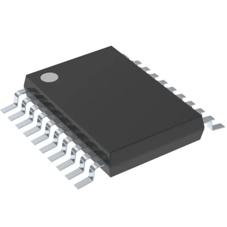
The MCP 2515 is a stand-alone controller area network (CAN) controller developed by Microchip Technology. It implements the CAN 2.0B protocol and supports transmitting and receiving standard and extended data and remote frames. The device features two acceptance masks and six acceptance filters to reject unwanted messages, reducing the processing workload of the host microcontroller (MCU). It communicates with the MCU through a standard Serial Peripheral Interface (SPI), making it suitable for embedded systems that require CAN connectivity without an integrated CAN controller. When paired with an external CAN transceiver, the MCP 2515 provides a practical solution for automotive, industrial, and microcontroller communication applications.
MCP2515 Specifications
The following table summarizes the main technical specifications of the MCP 2515 CAN controller.
Parameter | Value |
Manufacturer | Microchip Technology |
Base Product Number | MCP 2515 |
Protocol | CAN bus |
Function | Stand-alone CAN controller |
CAN Standard | CAN 2.0B |
Host Interface | SPI |
Maximum CAN Bit Rate | 1 Mb/s |
SPI Clock Frequency | Up to 10 MHz |
Supply Voltage | 2.7V~5.5V |
Typical Active Current | 5 mA |
Typical Standby Current | 1 μA |
Operating Temperature, Industrial | -40°C~85°C |
Operating Temperature, Extended | -40°C~125°C |
Receive Buffers | 2 |
Transmit Buffers | 3 |
Acceptance Filters | 6 |
Acceptance Masks | 2 |
Maximum Data Field | 8 bytes |
Package | 18-SOIC, 20-TSSOP, 20-QFN |
The MCP2515 is available in several package options. The MCP2515-I/SO uses an 18-pin SOIC package with a body width of approximately 7.50 mm, while the MCP2515-I/ST uses a 20-pin TSSOP package with a body width of approximately 4.40 mm. The exact package and should verify temperature grade when selecting a component for a new design.
Although the controller operates from a 2.7V~5.5V supply, the voltage requirements of the host MCU and external CAN transceiver must also consider. In particular, the logic-level compatibility between the MCP 2515, the MCU, and the transceiver should be checked before connecting the circuit.
MCP2515 Pinout
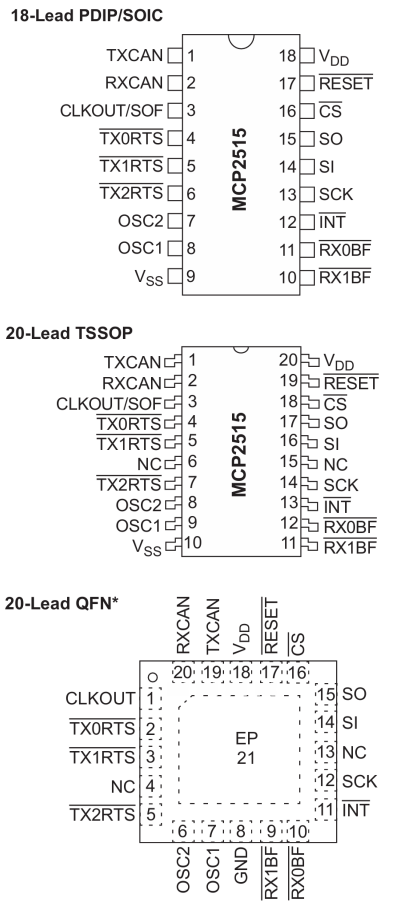
The component pinout includes CAN transmit and receive signals, SPI communication pins, oscillator connections, interrupt outputs, and power pins. The exact pin numbers depend on the package, so always refer to the appropriate package drawing before designing a PCB.
MCP2515 Pin Description
Pin Name | Function | Description |
TXCAN | CAN Transmit | Digital transmit output connected to the CAN transceiver |
RXCAN | CAN Receive | Digital receive input from the CAN transceiver |
CLKOUT | Clock Output | Provides a programmable clock output and can support start-of-frame monitoring |
TX0RTS | Transmit Request 0 | Requests transmission from transmit buffer 0 or serves as a configurable digital input |
TX1RTS | Transmit Request 1 | Requests transmission from transmit buffer 1 or serves as a configurable digital input |
TX2RTS | Transmit Request 2 | Requests transmission from transmit buffer 2 or serves as a configurable digital input |
OSC1 | Oscillator Input | Connects to the oscillator circuit or an external clock source |
OSC2 | Oscillator Output | Oscillator connection for the clock circuit |
VSS | Ground | Ground reference for logic and I/O |
RX0BF | Receive Buffer 0 Full | Indicates receive buffer 0 status or acts as a configurable digital output |
RX1BF | Receive Buffer 1 Full | Indicates receive buffer 1 status or acts as a configurable digital output |
INT | Interrupt Output | Signals selected events to the host MCU |
SCK | SPI Clock | Receives the SPI clock from the MCU |
SI | SPI Data Input | Receives serial data from the MCU; commonly called MOSI |
SO | SPI Data Output | Sends serial data to the MCU; commonly called MISO |
CS | Chip Select | Selects the controller for SPI communication; active low |
RESET | Reset Input | Active-low hardware reset |
VDD | Power Supply | Positive supply for the logic and I/O pins |
NC | No Connection | Pins identified as NC must be treated according to the package datasheet |
The SPI pins are essential for communication with the host microcontroller. SCK provides the clock, SI receives commands and data, SO returns register values and received information, and CS selects the MCP 2515 during an SPI transaction.
The INT pin can notify the MCU when a message arrives or another enabled event occurs. This allows the firmware to respond to communication events without continuously polling every status register. The TXCAN and RXCAN pins connect to the corresponding TXD and RXD signals of a compatible CAN transceiver, rather than directly to the CANH and CANL bus wires.
MCP 2515 Features
CAN 2.0B Protocol Support: The circuit implements the CAN 2.0B protocol at data rates up to 1 Mb/s. It supports standard and extended data and remote frames, with a data field length of 0~8 bytes.
Receive Buffers, Masks, and Filters: The controller provides two receive buffers with prioritized message storage, six 29-bit acceptance filters, and two 29-bit acceptance masks. These functions help filter unwanted messages and reduce MCU processing overhead. It also supports filtering the first two data bytes of standard data frames.
Three Transmit Buffers: Three transmit buffers support message prioritization and transmission-abort functions, allowing the host MCU to manage outgoing CAN messages efficiently.
High-Speed SPI Interface: The device supports an SPI clock frequency of up to 10 MHz and SPI modes 0,0 and 1,1, enabling efficient communication with a wide range of microcontrollers.
One-Shot Transmission Mode: This mode ensures that a message transmission is attempted only once, providing greater control over transmission retries.
Programmable Clock Output: The CLKOUT pin features a programmable prescaler and can supply a clock signal to other devices. It can also provide a Start-of-Frame (SOF) signal for time-slot-based protocols and CAN bus diagnostics.
Interrupt and I/O Functions: The MCP 2515 includes an interrupt output with selectable enable options. The receive-buffer-full pins can operate as interrupt outputs or general-purpose outputs, while the three Request-to-Send (RTS) pins can serve as transmission request inputs or general-purpose inputs.
Low-Power Operation: Operating from a 2.7V~5.5V supply, the controller typically consumes 5 mA in active mode and 1 μA in sleep mode, making it suitable for low-power embedded applications.
Wide Operating Temperature Range: Industrial-grade devices support -40°C~85°C, while applicable extended-temperature versions support -40°C~125°C.
MCP 2515 Applications
The MCP 2515 is useful in embedded systems that need CAN communication but do not include an integrated CAN controller. By combining an SPI interface with hardware message filtering and buffering, it can add CAN functionality without requiring a complete redesign of the host microcontroller system.
Automotive Electronics: The component enables CAN communication in vehicle monitoring systems, diagnostic tools, and electronic control units when paired with a compatible CAN transceiver.
Industrial Automation: It connects controllers, sensors, and monitoring devices through CAN networks, supporting reliable data exchange in industrial systems.
Robotics: The controller enables communication between microcontrollers, motor drivers, and CAN-compatible sensors for exchanging commands and status information.
Arduino and ESP32 Projects: The MCP 2515 CAN bus module adds CAN connectivity to Arduino, ESP32, and STM32 boards through an SPI interface.
Sensor Networks: It supports transmitting sensor readings and equipment status while using hardware filters to reduce unnecessary message processing.
MCP2515 Can Bus Module TJA1050 Board
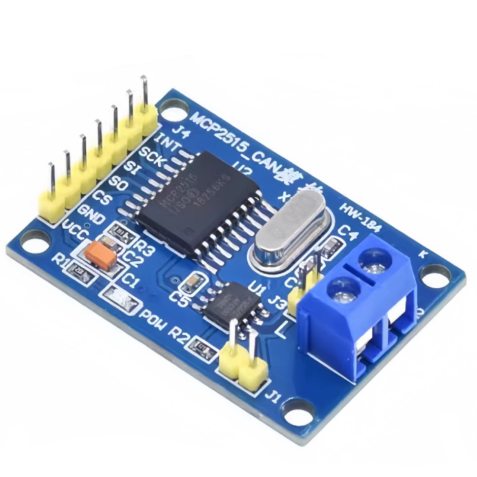
The MCP 2515 TJA1050 CAN bus module combines the MCP2515 stand-alone CAN controller with the TJA 1050 CAN transceiver. This board allows a microcontroller to communicate with a physical CAN network through SPI, making it useful for prototyping and embedded development.
MCP2515 TJA1050 Module Specifications
Parameter | Value |
CAN Controller | MCP2515 |
CAN Transceiver | TJA1050 |
Communication Protocol | CAN 2.0B |
Maximum CAN Bit Rate | Up to 1 Mb/s |
Host Interface | SPI |
Module Supply | Typically 5 V DC |
Data Field | 0~8 bytes |
Supported Frames | Standard, extended, and remote frames |
Termination | 120 Ω resistor, if fitted |
Typical Controller Current | Approximately 5 mA, excluding indicator and other board loads |
Operating Temperature | -40°C~85°C, depending on component ratings |
Module Dimensions | Approximately 44 mm × 28 mm |
Mounting Hole Center Distance | Approximately 38 mm × 23 mm |
How the Module Works
The MCP2515 handles CAN protocol operations, including message transmission, reception, filtering, and buffering. The TJA1050 converts the controller's TXCAN and RXCAN logic signals into the differential CANH and CANL signals required by the physical bus.
The MCU communicates with the controller over SPI. When the firmware sends a message, the MCP2515 prepares and transmits the CAN frame through the TJA1050. Incoming frames travel in the opposite direction and are stored in the controller's receive buffers for the MCU to retrieve.
Wiring Considerations
Connect the module's SPI clock, MOSI, MISO, and chip-select pins to the corresponding SPI connections on the MCU. Connect the interrupt pin if the firmware uses interrupt-driven reception. Supply the module according to its specifications and connect its ground to the MCU ground.
The CANH and CANL terminals connect to the corresponding differential bus wires. A CAN network normally requires 120 Ω termination at each physical end of the bus, not at every node. Before adding a termination resistor, check whether the module already has one installed.
Although many modules are advertised for Arduino, Raspberry Pi, ESP32, and STM32 projects, compatibility depends on the module's logic levels, power requirements, driver support, and SPI configuration. In particular, a 5 V-powered module must not be assumed to have 3.3 V-safe signals on every pin. Check the circuit and component specifications before connecting it to a 3.3 V MCU.
Comparison of CAN over SPI and I2C
SPI and I2C are host-side communication interfaces. They are not substitutes for the CAN protocol itself. The MCP2515 uses SPI to communicate with the host MCU, while the CAN transceiver provides the electrical interface to the CAN bus.
A typical CAN communication chain is:
Host MCU → SPI → MCP2515 CAN controller → TJA1050 CAN transceiver → CANH/CANL bus
SPI vs. I2C Comparison
Parameter | SPI | I2C |
Signal Lines | SCK, MOSI, MISO, CS | SCL, SDA |
Communication Type | Synchronous serial | Synchronous serial |
Device Selection | Chip-select signal | Device address |
Typical Topology | Controller with selected peripherals | Shared two-wire bus |
Full-Duplex Capability | Supported | Generally half-duplex |
Protocol Overhead | Typically low | Includes address and acknowledgment overhead |
Typical Advantages | High throughput and simple transfers | Fewer signal wires and convenient shared-bus connections |
Common Uses | Displays, memory, ADCs, CAN controllers | Sensors, EEPROMs, expanders, RTCs |
MCP2515 Interface | Supported | Not supported natively |
SPI is a suitable choice for the MCP2515 because it provides an efficient way to access registers and move CAN messages between the controller and the host MCU. Its dedicated chip-select signal also makes it straightforward to connect the device alongside other SPI peripherals.
I2C can be advantageous when a design needs to connect several low-speed peripherals using only two signal lines. However, the MCP2515 does not provide a native I2C host interface. An I2C-to-SPI bridge or an additional microcontroller could be used as an intermediary, but this adds complexity and is generally unnecessary when the host already supports SPI.
It is also important to distinguish the host interface from the CAN bus. SPI and I2C connect local electronic components, whereas CAN uses a differential physical layer and a message-based protocol designed for communication between network nodes.
Frequently Asked Questions
What is the purpose of the MCP2515 canbus?
The MCP 2515 adds CAN 2.0B communication to a microcontroller through SPI. It manages CAN messages, transmit and receive buffers, acceptance filters, and protocol-related operations. With an external CAN transceiver, it allows an MCU without a built-in CAN controller to send and receive messages on a compatible CAN network.
What does MCP2515 do?
The MCP2515 receives commands and data from a host MCU over SPI, constructs CAN frames for transmission, and stores incoming CAN messages in receive buffers. It also filters messages using acceptance masks and filters. Require a separate CAN transceiver to connect the controller to the CANH and CANL physical bus.
Is MCP2515 reliable?
The MCP2515 is a widely used controller for CAN 2.0B embedded applications. Its hardware buffering, message filtering, and interrupt functions support dependable communication when configured correctly. Reliability also depends on oscillator accuracy, CAN bit timing, proper termination, wiring, power integrity, transceiver selection, and the electromagnetic conditions of the application.
CAN bus shield MCP2515?
An MCP 2515 CAN bus shield is an expansion board that adds CAN communication to a compatible development board, commonly an Arduino. It typically contains an MCP2515 controller and a CAN transceiver, along with supporting components and a CAN connector. Check the shield's pin mapping, operating voltage, and termination before connecting it.
CAN bus MCP2515 module?
An MCP2515 CAN bus module is a compact circuit board containing the MCP2515 controller and usually a CAN transceiver such as the TJA1050. The MCU accesses the controller through SPI, while the transceiver connects to CANH and CANL. These modules are used in prototyping, embedded control, and CAN monitoring projects.
Does MCP2515 support CAN FD?
No. The MCP 2515 supports Classical CAN 2.0B, with a maximum payload of 8 bytes per frame. It does not support CAN FD frames or their larger payloads. If an application requires CAN FD, select a controller specifically designed for CAN FD and ensure the transceiver and the rest of the network support the required operating modes.
What is the cost of an MCP2515 CAN module?
The price of an MCP2515 CAN module depends on the transceiver, PCB design, connector type, termination components, seller, and order quantity. Basic modules are generally economical, but current prices vary by supplier and location. Compare the module's voltage compatibility, included transceiver, oscillator, termination resistor, and documentation before choosing one for a project.
Conclusion
The MCP2515 is a practical stand-alone CAN controller for embedded systems that require Classical CAN communication through an SPI interface. Its support for CAN 2.0B, three transmit buffers, two receive buffers, six acceptance filters, and two acceptance masks helps simplify CAN message handling while reducing the workload on the host MCU.
When paired with a compatible CAN transceiver such as the TJA1050, it provides a convenient way to add CAN connectivity to Arduino, STM32, ESP32, and other microcontroller-based projects. For successful integration, verify the package pinout, supply voltage, logic-level compatibility, oscillator configuration, bit timing, and CAN bus termination. For applications requiring CAN FD, choose a controller that explicitly supports that protocol.
Read More:
1. CC1101 Wireless RF Transceiver Module Board Guide
2. Mini MP1584 DC-DC 3A Buck Converter Module: Complete Guide
3. JRC4558 Operational Amplifier (Op-Amp) Guide
MCP2515 Datasheet:
HOT NEWS
TP4056 Charging Module Pinout, Working, and Applications
TP4056 Charging Module Pinout, Working, and Applications
2026-01-23
LR41 Battery Guide: Specifications, Equivalents, and Uses
LR41 Battery Specifications, Equivalents, and Uses
2025-12-14
Understanding A 0603 Resistor
0603 resistor,dimensions,marking code, values
2025-05-29
Understanding The CD4051 Analog Multiplexer
CD4051 analog multiplexer
2025-06-30
MT3608 Boost Converter - An In-Depth Guide
MT3608 Boost Converter
2025-09-04
Complete Guide to the 220 Ohm Resistor
220 Ohm Resistor
2025-07-28
The 0402 Resistor: A Comprehensive Guide
0402 Resistor
2025-05-06
What Is A 1206 Resistor?
1206 resistor dimensions,footprint,value
2025-06-05
Guide To The XL6009 Boost Converter
XL6009 Boost Converter
2025-09-05
Mini MP1584 DC-DC 3A Buck Converter Module: Complete Guide
Mini MP1584 DC-DC 3A Buck Converter Module: Complete Guide
2026-03-26