




 BOM
BOM Cart
Cart Product Catalog
The MCP2551 is a high-speed CAN-transceiver designed to connect a CAN protocol controller to a physical Controller Area Network (CAN) bus. It converts digital transmit and receive signals into differential bus signals, enabling reliable communication between microcontrollers, automotive electronics, industrial controllers, and other CAN-enabled devices. Supporting communication speeds of up to 1 Mb/s, this device provides noise immunity, fault protection, and compatibility with the ISO 11898 physical-layer standard.
This guide covers the MCP2551 transceiver description, pinout, functional features, electrical specifications, equivalent components, working principle, module connections, and frequently asked questions to help you select and integrate it into a CAN communication system.
1. MCP2551 Transceiver Description
6. Applications and Working Principle
7. MCP2551 Can Transceiver Module
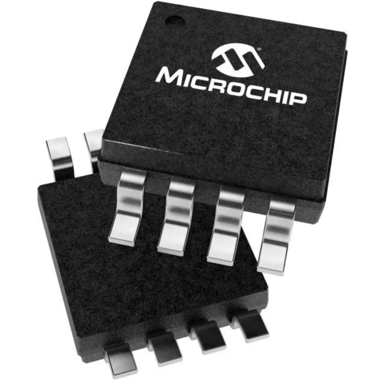
MCP2551 Transceiver Description
The MCP 2551 is a high-speed CAN transceiver manufactured by Microchip Technology. It serves as the interface between a CAN protocol controller and the physical CAN bus, providing differential transmission and reception of CAN data. The device supports data rates of up to 1 Mb/s and is designed for CAN networks that require reliable communication in electrically noisy environments.
In a typical CAN system, a microcontroller or dedicated CAN-controller generates digital transmit data. The transceiver converts this logic-level data into differential signals on the CANH and CANL lines. In the receiving direction, it detects the differential voltage on the bus and converts it into a logic-level signal for the CAN controller.
The MCP 2551 is compatible with the ISO 11898 physical-layer requirements and is suitable for systems using 12 V and 24 V electrical supplies, provided the transceiver itself receives its specified supply voltage. Its differential signaling improves immunity to electromagnetic interference (EMI), while its protective circuitry helps the device withstand electrical transients, electrostatic discharge (ESD), and certain short-circuit conditions.
The transceiver also incorporates thermal shutdown, undervoltage-related protection, and standby operation. These functions help protect the device and maintain CAN bus stability during certain fault conditions. An unpowered node or a brownout event is designed not to disturb communication on the bus, making the MCP 2551 useful in automotive electronics, industrial automation, and embedded CAN networks.
MCP2551 Pinout
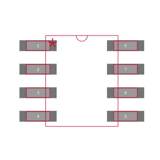
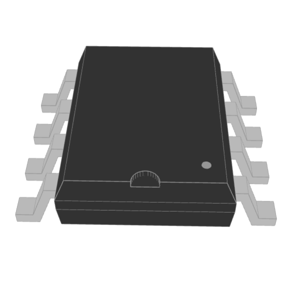
The MCP 2551 is available in an 8-pin SOIC package. Its pins provide power, ground, transmit and receive signals, a reference voltage output, CAN bus connections, and slope control.
MCP 2551 Pin Configuration
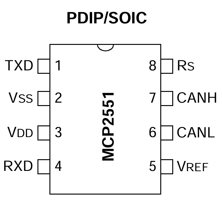
Pin Number | Pin Name | Description |
1 | TXD | Transmit data input from the CAN controller |
2 | VSS | Ground connection |
3 | VDD | Positive supply voltage |
4 | RXD | Receive data output to the CAN controller |
5 | VREF | Reference voltage output |
6 | CANL | CAN low differential bus line |
7 | CANH | CAN high differential bus line |
8 | RS | Slope-control and standby-mode input |
MCP2551 Functional Block Diagram
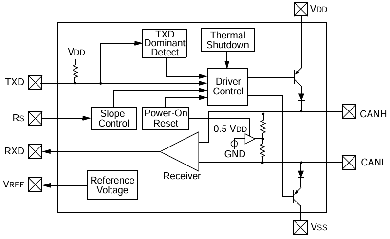
MCP2551 CAD Model
Symbol
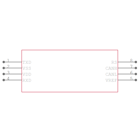
Footprint
3D Model
MCP2551 Features
The MCP 2551 combines high-speed CAN communication with electrical protection and configurable signal-transition behavior. These features make it suitable for systems where multiple electronic nodes exchange data over a shared differential bus.
Feature | Description |
Maximum data rate | Up to 1 Mb/s |
Physical-layer standard | ISO 11898 |
System compatibility | Suitable for 12 V and 24 V systems |
Slope control | External control to reduce radio-frequency interference |
TXD fault detection | Detects a permanent-dominant condition on TXD |
Power protection | Power-on reset and brownout-related protection |
Bus fault tolerance | An unpowered or brownout-affected node is designed not to disturb the bus |
Standby operation | Low-current standby mode |
Short-circuit protection | Protection against specified positive and negative battery short conditions |
Transient protection | Protection against high-voltage transients within device ratings |
Thermal protection | Automatic thermal shutdown |
Network capacity | Up to 112 nodes under supported network conditions |
Noise immunity | Differential signaling reduces susceptibility to common-mode noise |
Industrial temperature | -40°C~+85°C |
Extended temperature | -40°C~+125°C |
The slope-control function allows the rate of signal transitions to be adjusted to help reduce electromagnetic emissions. This can be useful in systems with strict electromagnetic compatibility requirements, although the selected setting must still support the required communication speed and bus conditions.
The built-in protection features improve reliability, but they do not eliminate the need for appropriate PCB layout, decoupling, bus termination, grounding, and external protection where the application requires it.
MCP2551 Specifications
The following table summarizes the main component specifications and ordering information.
Parameter | Value |
Manufacturer | Microchip Technology |
Type | CAN transceiver |
Protocol | CAN bus |
Number of drivers/receivers | 1/1 |
Duplex | Half-duplex |
Receiver hysteresis | 200 mV |
Supply voltage | 4.5V~5.5V |
Operating temperature, industrial | -40°C~+85°C |
Operating temperature, extended | -40°C~+125°C for the specified E-grade variant |
Mounting type | Surface mount |
Package/case | 8-SOIC, 3.90 mm width |
Supplier package | 8-SOIC |
Packaging | Tube |
Base product number | MCP 2551 |
Example ordering codes | MCP2551-I/SN, MCP2551-E/SN |
The MCP 2551 requires a supply voltage of 4.5V~5.5V. Although it can interface with CAN networks used in 12 V and 24 V systems, those figures describe the vehicle or system environment, not the IC's direct supply voltage.
When choosing between the I-grade and E-grade parts, verify the exact ordering code and manufacturer datasheet. Temperature grades and other ordering characteristics should not be assumed to be interchangeable.
MCP2551 Alternatives & Equivalents
Can consider several CAN transceivers as alternatives to the MCP2551. The right replacement depends on supply voltage, maximum data rate, standby behavior, fault protection, package, and pin compatibility.
ATA6561
The ATA6561 is a CAN transceiver option for embedded and automotive communication systems. It can be considered when designing a newer CAN interface, but its supply requirements, operating modes, protection characteristics, and package must be checked against the original design before replacement.
ATA6562
The ATA6562 is another Microchip CAN transceiver that may suit applications requiring reliable communication over a differential bus. Compare its electrical characteristics and pin configuration with the existing circuit before substituting it for the MCP 2551.
ATA6560
The ATA6560 is another candidate for CAN communication designs. Engineers should compare its supported CAN data rates, standby features, fault protection, and package requirements with the existing hardware.
MAX13052
The MAX13052 is a CAN transceiver option for systems requiring differential CAN communication. Before selecting it, confirm the precise device variant, supply-voltage compatibility, bus-fault ratings, and PCB footprint.
LTC2875
The LTC2875 belongs to the family of industrial interface transceivers. Its suitability depends on the exact interface and application requirements; it should not be treated as a drop-in MCP 2551 replacement without checking its datasheet.
PCA82C250
The PCA82C250 is an older high-speed CAN transceiver used in legacy embedded and automotive designs. It may be relevant when maintaining existing CAN hardware, but differences in pinout, electrical behavior, and should consider availability.
Replacement note: Similar CAN functionality does not guarantee pin-to-pin compatibility. Check the manufacturer's datasheets for electrical limits, bus compatibility, package dimensions, and logic-level requirements before replacing the MCP2551.
MCP2551 Applications and Working Principle
Application
The MCP 2551 is used in applications that require reliable communication between electronic control units over a shared CAN network. Its differential signaling and built-in protection features make it useful in automotive electronics, industrial control, embedded systems, and data acquisition equipment.
In automotive applications, the transceiver can connect a CAN controller to an in-vehicle network for exchanging information among electronic control units, dashboard systems, diagnostic equipment, and body-control modules. It is also suitable for certain 12 V and 24 V vehicle electrical environments when the overall circuit is designed within the device's specifications.
In industrial automation, the device can provide the physical interface for programmable controllers, monitoring systems, motor-control equipment, and distributed sensors. Differential communication helps reduce the effects of electrical noise that may be present around motors, relays, and switching power supplies.
For embedded development, the MCP 2551 can connect a microcontroller with an integrated CAN controller to a CAN bus. It is commonly paired with a separate CAN controller, such as the MCP2515, when the microcontroller does not have a built-in CAN peripheral.
Other applications include CAN-based data loggers, test equipment, communication gateways, and robotics systems. Proper bus termination, wiring, grounding, and supply decoupling remain important for stable operation.
How Does the MCP2551 Work?
The MCP 2551 works as a physical-layer interface rather than a complete CAN protocol controller. It translates digital logic signals into differential electrical signals and performs the reverse conversion when receiving data.
Step 1: CAN controller generates data
The CAN controller formats messages, manages arbitration and error handling, and sends serialized transmit data to the MCP 2551 through TXD.
Step 2: Transceiver drives the bus
The MCP 2551 converts the digital signal into differential signals on CANH and CANL. The difference between the two bus-line voltages represents the dominant and recessive states.
Step 3: Data travels across the network
The differential signal propagates along the shared CAN bus, allowing connected nodes to monitor the transmitted information.
Step 4: Receiver converts the signal
The receiving transceiver detects the differential bus state and outputs a corresponding logic signal through RXD to its CAN controller.
The CAN bus uses two logical states. A dominant bit overrides a recessive bit when multiple nodes transmit simultaneously, supporting CAN's nondestructive arbitration mechanism. The MCP2551 implements the electrical interface that makes these bus states possible; the CAN controller handles the protocol-level operations.
Basic MCP2551 Connection
A typical circuit connects the transceiver to a CAN controller and then to the two-wire CAN bus.
MCP2551 Pin | Connection |
TXD | CAN controller transmit output |
RXD | CAN controller receive input |
VSS | Circuit ground |
VDD | Regulated 5 V supply within the specified range |
CANH | CAN bus high |
CANL | CAN bus low |
VREF | Reference output; use only as required by the circuit |
RS | Slope-control or standby configuration |
Use a suitable decoupling capacitor close to VDD and VSS. Terminate the bus according to the network topology, normally with 120 Ω at each physical end of a conventional high-speed CAN bus. Avoid adding termination at every node.
Also verify that the controller's logic levels are compatible with the MCP 2551. In particular, a 3.3 V microcontroller interface should check carefully because the MCP2551 is a 5 V-powered device. Do not assume every logic pin is 3.3 V compatible.
MCP2551 Can Transceiver Module
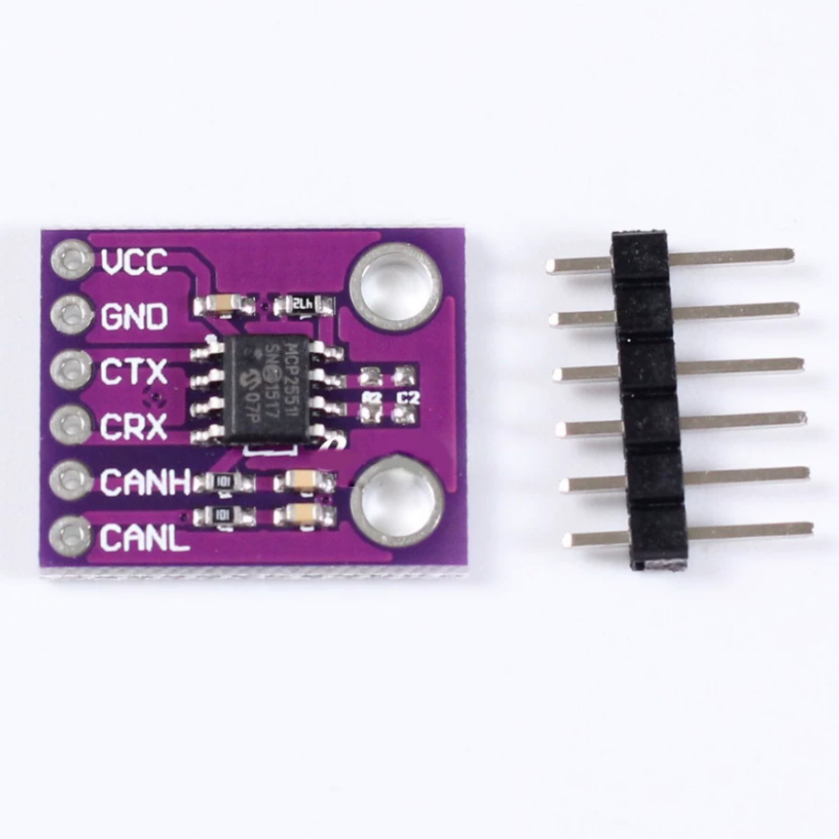
The MCP 2551 CAN transceiver module provides a convenient way to connect a CAN controller to a physical CAN bus without designing the transceiver circuitry from individual components. Depending on the board design, the module may include the MCP2551 IC, supporting components, and accessible connection pins.
The module performs the same core function as the standalone IC: it converts the CAN controller's digital transmit and receive signals into differential CAN bus signals. It supports communication rates of up to 1 Mb/s when the controller, wiring, bus length, and network configuration permit.
MCP2551 Module Features
Parameter | Description |
Main chip | MCP2551 |
Interface | CAN bus |
Maximum data rate | Up to 1 Mb/s |
Signal connections | TXD, RXD, CANH, CANL |
Supply | Typically 5 V for the MCP2551 IC; verify the module rating |
Applications | Automotive electronics, industrial control, embedded CAN networks |
Bus wiring | CANH and CANL differential pair |
Frequently Asked Questions
CAN SPI MCP2515 Arduino?
Yes. The MCP2515 can connect to an Arduino through SPI, while an MCP2551 or another compatible CAN transceiver provides the physical bus interface. Many CAN modules combine both chips. The Arduino requires a suitable library and correct SPI, interrupt, supply, and bus-termination configurations.
CAN bus shield V2 adopts MCP2515 and MCP2551?
Many CAN shields use an MCP2515 CAN controller and an MCP2551 physical-layer transceiver, but the exact components depend on the manufacturer and hardware revision. Some newer shields use different transceivers. Check the board schematic or component markings before selecting libraries, wiring the shield, or determining its electrical compatibility.
How do CAN bus system work?
A CAN bus connects multiple nodes through a shared differential pair, CANH and CANL. Each node uses a CAN controller to construct and process messages and a transceiver to communicate electrically with the bus. Message identifiers determine arbitration priority, allowing higher-priority messages to win access without corrupting the winning transmission.
How does MCP2551 transceiver implement CAN protocol control and physical bus interface?
The MCP2551 receives serialized digital data from the controller through TXD and converts it into differential signals on CANH and CANL. During reception, it detects the differential bus state and returns a corresponding logic signal through RXD. This separates protocol processing from physical signal transmission and reception.
What is the difference between MCP2551 and TJA1050?
Both devices are high-speed CAN transceivers that connect CAN controllers to differential CAN buses. However, their supply requirements, electrical characteristics, operating modes, protection features, and package details may differ. They should not automatically consider pin-compatible. Check the respective datasheets and the intended operating environment before choosing a replacement.
What is the difference between MCP2551 and TJA1050?
The SN65HVD251P is another high-speed CAN transceiver, but replacement suitability depends on supply voltage, logic compatibility, pin assignment, bus-fault ratings, and operating temperature. Compare the two datasheets and verify the circuit requirements before substitution. Similar CAN functionality alone does not guarantee that the SN65HVD251P can be installed directly in an MCP2551 footprint.
Conclusion
The MCP2551 is a high-speed CAN transceiver that provides the differential physical-layer interface between a CAN controller and a shared CAN bus. With data rates up to 1 Mb/s, configurable slope control, standby operation, and built-in protection features, it is useful in automotive electronics, industrial automation, and embedded communication systems.
When designing a CAN interface, pay particular attention to supply voltage, logic-level compatibility, bus termination, wiring, and the operating-temperature grade. For systems using an Arduino or another microcontroller without an integrated CAN controller, pairing an MCP2515 with an appropriate transceiver is a practical way to implement CAN communication.
Read More:
1. MCP2515 CAN Bus Controller: Pinout, Guide and Module Board
2. SN65HVD230: IC Specification & CAN Transceiver Module Board
3. LCD1602 Display Module 1602A 16X2 Compatible with Arduino R3 Mega2560 Raspberry Pi
MCP2551 Datasheet:
MCP2551-I/SN, MCP2551-E/SN, MCP2551T-I/SN, MCP2551T-E/SN, MCP2551-I/P, MCP2551-E/P PDF data sheet
HOT NEWS
TP4056 Charging Module Pinout, Working, and Applications
TP4056 Charging Module Pinout, Working, and Applications
2026-01-23
LR41 Battery Guide: Specifications, Equivalents, and Uses
LR41 Battery Specifications, Equivalents, and Uses
2025-12-14
Understanding A 0603 Resistor
0603 resistor,dimensions,marking code, values
2025-05-29
Understanding The CD4051 Analog Multiplexer
CD4051 analog multiplexer
2025-06-30
MT3608 Boost Converter - An In-Depth Guide
MT3608 Boost Converter
2025-09-04
Complete Guide to the 220 Ohm Resistor
220 Ohm Resistor
2025-07-28
The 0402 Resistor: A Comprehensive Guide
0402 Resistor
2025-05-06
Guide To The XL6009 Boost Converter
XL6009 Boost Converter
2025-09-05
What Is A 1206 Resistor?
1206 resistor dimensions,footprint,value
2025-06-05
Mini MP1584 DC-DC 3A Buck Converter Module: Complete Guide
Mini MP1584 DC-DC 3A Buck Converter Module: Complete Guide
2026-03-26