




 BOM
BOM Cart
Cart Product Catalog
The PCA9685 is a 16-channel, 12-bit PWM controller designed for applications that require multiple independently controlled PWM outputs. Using an I2C interface, it allows a microcontroller such as Arduino, ESP32, or Raspberry Pi to control up to 16 PWM channels while reducing the number of GPIO pins required. With 4096-step resolution and a programmable PWM frequency, the PCA9685 widely use for LED brightness control, RGB lighting, LCD backlighting, and multi-servo projects.
6. PCA9685 16-Channel 12-Bit PWM Servo Driver Module Board
7. How to Use PCA9685 with Arduino?
8. Frequently Asked Questions [FAQ]
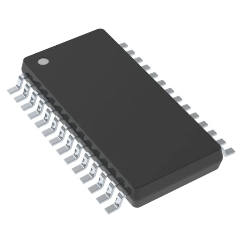
What is PCA9685?
The PCA9685 is an I2C-controlled 16-channel, 12-bit PWM LED controller designed for LED dimming, RGB/RGBA backlighting, and multi-channel PWM applications. Each of its 16 outputs provides 4096-step brightness control with a programmable PWM frequency from approximately 24 Hz to 1526 Hz and a 0% to 100% duty cycle. All channels operate at the same PWM frequency while their duty cycles can adjust independently.
The PCA 9685 operates from 2.3 V to 5.5 V and provides 5.5 V-tolerant inputs and outputs. Can configure its LED drivers as open-drain or totem-pole outputs. An internal 25 MHz oscillator eliminates the need for external timing components, while an external clock input up to 50 MHz supports synchronization between devices. The active-low OE pin provides quick output control, and hardware and software addressing allows multiple PCA 9685 devices to share an I2C bus.
PCA9685 Pinout
The PCA9685 is available in a 28-pin TSSOP package and HVQFN28 package. The following table shows the main TSSOP28 pin assignments.
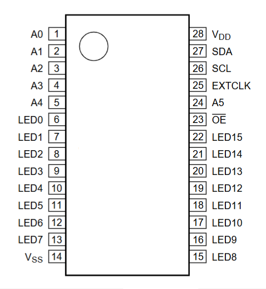
Symbol | Pin | Type | Description |
A0 | 1 | I | Address input 0 |
A1 | 2 | I | Address input 1 |
A2 | 3 | I | Address input 2 |
A3 | 4 | I | Address input 3 |
A4 | 5 | I | Address input 4 |
LED0 | 6 | O | LED driver 0 |
LED1 | 7 | O | LED driver 1 |
LED2 | 8 | O | LED driver 2 |
LED3 | 9 | O | LED driver 3 |
LED4 | 10 | O | LED driver 4 |
LED5 | 11 | O | LED driver 5 |
LED6 | 12 | O | LED driver 6 |
LED7 | 13 | O | LED driver 7 |
VSS | 14 | Power | Supply ground |
LED8 | 15 | O | LED driver 8 |
LED9 | 16 | O | LED driver 9 |
LED10 | 17 | O | LED driver 10 |
LED11 | 18 | O | LED driver 11 |
LED12 | 19 | O | LED driver 12 |
LED13 | 20 | O | LED driver 13 |
LED14 | 21 | O | LED driver 14 |
LED15 | 22 | O | LED driver 15 |
OE | 23 | I | Active-low output enable |
A5 | 24 | I | address input 5 |
EXTCLK | 25 | I | External clock input |
~SCL | 26 | I | serial clock line |
~SDA | 27 | I/O | serial data line |
VDD | 28 | Power | Supply voltage |
Address Pins
The A0 to A4 address pins are used to select the I2C address of the PCA9685. Depending on the module design and address configuration, can connect multiple PCA9685 boards to the same I2C bus.
LED0 to LED15
The LED0 to LED15 outputs provide 16 independent PWM channels. They can use for LED brightness control or for generating PWM signals for devices such as servo motors.
SDA and SCL
SDA is the I2C data line and SCL is the I2C clock line. Only require these two communication lines between the PCA9685 and a microcontroller, together with power and ground.
OE
The OE pin is an active-low output-enable input. When OE is high, the LED outputs can be disabled or placed into the programmed high-impedance state. It can also be toggled to provide hardware control over simultaneous LED blinking or dimming.
EXTCLK
The EXTCLK pin accepts an external clock source up to 50 MHz. An external clock can be useful when several PCA 9685 devices need synchronized PWM operation.
PCA 9685 Specifications
Table
Parameter | Value |
Device type | 16-channel PWM LED controller |
PWM resolution | 12-bit, 4096 steps |
Number of PWM channels | 16 |
Interface | I2C-bus |
Maximum I2C frequency | 1 MHz |
Supply voltage | 2.3 V~5.5 V |
Input/output tolerance | 5.5 V |
PWM frequency | Typically 24 Hz~1526 Hz |
Default PWM frequency | Approximately 200 Hz |
Internal oscillator | 25 MHz typical |
External clock | Up to 50 MHz |
Output sink current | 25 mA at 5 V |
Output source current | 10 mA at 5 V |
Output modes | Totem pole / open drain |
Hardware address pins | 6 |
Maximum devices per I2C bus | 62 |
Maximum PWM outputs with 62 devices | 992 |
Operating temperature | -40°C~+85°C |
Package | TSSOP28, HVQFN28 |
The PCA9685 12-bit PWM resolution provides 4096 individual PWM steps. This gives considerably finer control than an 8-bit PWM controller, which provides only 256 steps.
The PWM frequency is programmable, allowing the same controller to use for LED dimming, backlighting, and servo applications. The default PRE_SCALE setting with the typical 25 MHz oscillator produces a PWM refresh rate of approximately 200 Hz.
PCA9685 Applications
Can use the PCA 9685 in many systems where a microcontroller needs a large number of independently controlled PWM channels.
RGB and RGBA LED Drivers
Can control individual red, green, blue, and amber LED channels. Its 12-bit PWM resolution allows smooth brightness adjustment and color mixing.
LED Status Indicators
Multiple LED indicators can be controlled independently from a single I2C interface. The PWM channels can provide different brightness levels for status indicators.
LED Displays
The 16 PWM outputs are useful for controlling LED display elements that require independent brightness control.
LCD Backlighting
The programmable PWM frequency and brightness resolution make the PCA 9685 suitable for LCD and other backlight applications.
Keypad Backlighting
The component can provide independent PWM control for keypad or handheld-device backlighting while reducing the number of microcontroller GPIO pins required.
Servo Control
PCA 9685 modules are widely used in robotics and multi-servo projects. A single board provides 16 PWM outputs, allowing many servo control signals to be generated without requiring 16 dedicated MCU PWM peripherals.
PCA9685 Features
16 Independent PWM Channels
The chip provides 16 LED/PWM driver outputs. Can program every output independently as fully off, fully on, or at a selected PWM duty cycle.
12-Bit PWM Resolution
Each output provides 4096 PWM steps, allowing fine control of LED brightness and PWM pulse width. The high resolution is also useful for applications that require precise servo positioning.
Programmable PWM Frequency
The PWM frequency for all outputs can typically adjust from approximately 24 Hz to 1526 Hz. This is significantly more flexible than controllers with a fixed PWM frequency.
I2C Interface
The PCA 9685 uses a two-wire I2C interface. SDA and SCL connect the controller to the host microcontroller, while the PCA9685 internally generates the PWM signals.
Fast-Mode Plus Support
The device supports the I2C Fast-mode Plus specification with communication speeds up to 1 MHz and high-drive capability on the SDA output for systems with higher bus capacitance.
Programmable Output Timing
The PCA9685 can independently program the turn-on and turn-off timing of its 16 channels. Staggering output transitions can help reduce simultaneous current surges in LED applications.
Totem-Pole and Open-Drain Outputs
The LED outputs can be configured for totem-pole or open-drain operation. Totem-pole outputs can sink up to 25 mA and source up to 10 mA at 5 V.
External Clock Input
An external clock of up to 50 MHz can be connected through EXTCLK. This makes it possible to synchronize multiple PCA 9685 controllers when require consistent PWM timing.
Output Enable Control
The active-low OE input can disable the outputs quickly. It can also be toggled to control multiple outputs simultaneously for hardware-based blinking or dimming.
Multiple Device Addressing
The PCA 9685 provides hardware address selection and software-programmable group addresses. Up to 62 PCA9685 devices can share one I2C bus, providing up to 992 PWM channels.
Software Reset
The SWRST General Call function allows the I2C master to reset the PCA 9685 through the bus. This provides a convenient method for returning the device registers to their default state.
PCA9685 16-Channel 12-Bit PWM Servo Driver Module Board
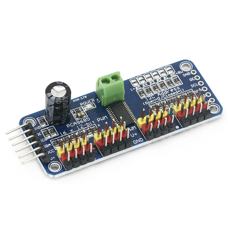
The PCA 9685 16-channel servo driver module is an I2C-based controller board with an integrated PWM driver and clock, allowing the microcontroller to control multiple PWM channels without continuously generating PWM-signals in software. This reduces the processing load on the host controller and makes the board suitable for multi-servo and LED control applications.
The module supports 16 PWM output channels with 12-bit resolution, providing 4096 steps for precise PWM control. Its PWM frequency is adjustable up to approximately 1.6 kHz, making it suitable for applications such as servo positioning, LED dimming, and RGB lighting.
The PCA9685 is compatible with 3.3 V and 5 V logic systems, making it suitable for microcontrollers such as Arduino and ESP32. Six hardware address pins allow multiple boards to share the same I2C bus. Can connect up to 62 devices, providing as many as 992 PWM outputs.
PCA9685 Module Features
Feature | Description |
Controller IC | PCA9685 16-channel PWM controller |
Communication | I2C interface |
PWM Channels | 16 independent channels |
PWM Resolution | 12-bit, 4096 steps |
PWM Frequency | Adjustable, up to approximately 1.6 kHz |
Logic Compatibility | Suitable for 3.3 V and 5 V logic systems |
I2C Addressing | 6 hardware address-selection pins |
Multiple Modules | Up to 62 PCA9685 devices on one I2C bus |
Total PWM Outputs | Up to 992 channels with 62 modules |
Output Mode | Configurable totem-pole or open-drain |
Output Enable | OE pin for quickly disabling all outputs |
Servo Connectors | 16 servo channels through four groups of 3-pin connectors |
Power Input | External power input terminal |
Power Indicator | Green LED |
Protection | Input reverse-polarity protection |
Cascading | Supports multiple modules |
Bulk Capacitor | Large capacitor provided on the V+ power rail |
Output Protection | 220 Ω series resistor on each PWM output |
Typical Applications | Servo control, LED dimming, RGB lighting, robotics |
Module Size | 25 mm × 61 mm |
How to Use PCA9685 with Arduino?
The PCA9685 connects to an Arduino through the I2C interface. Only require the I2C communication lines and power connections for communication.
For an Arduino Uno, the typical connections are:
PCA9685 | Arduino Uno |
VCC | 5V |
GND | GND |
SDA | A4 |
SCL | A5 |
Connect the servo or LED load to the PCA 9685 output channels. When using servos, connect their power to the module's V+ and GND terminals rather than relying on the Arduino 5 V output.
The Arduino sends commands through I2C to configure the PWM frequency and individual channel values. The PCA9685 then generates the PWM signals independently.
For servo applications, the PWM frequency is commonly configured around 50 Hz, although the appropriate value should be selected according to the servo specifications.
For LED applications, can select the PWM frequency according to the LED driver and visual requirements.
Basic Arduino Connection
The general connection is:
Arduino → I2C → PCA9685 → Servo/LED
The Arduino handles high-level control while the PCA9685 handles the 16 PWM channels. This arrangement greatly reduces the number of GPIO and hardware PWM resources required from the Arduino.
Frequently Asked Questions [FAQ]
What is the PCA9685 module?
The PCA9685 module is a 16-channel PWM driver board based on the PCA9685PW IC. It communicates through I2C and provides 16 independently programmable 12-bit PWM outputs. It is commonly used for controlling servos, LEDs, RGB lighting, displays, and other PWM devices.
How much current can PCA9685 handle?
The PCA9685 output drivers can sink up to 25 mA at 5 V. In totem-pole mode, an output can source up to 10 mA at 5 V. These specifications apply to the IC output drivers, while the current capability of a particular module also depends on its PCB design and connected power supply.
How do I set up the PCA9685?
Connect VCC and GND, then connect SDA and SCL to the microcontroller's I2C interface. Set the desired I2C address, configure the PWM frequency, and assign PWM values to the required channels. For servos, use a suitable external supply connected to the module's V+ terminal.
How to connect PCA9685 to esp32?
Connect the PCA9685 VCC to the ESP32-compatible logic supply, connect GND to GND, and connect SDA and SCL to the ESP32 I2C pins. GPIO21 and GPIO22 are commonly used for SDA and SCL on many ESP32 boards. Use a separate supply for multiple servos.
How to use PCA9685 with Raspberry Pi 4?
Connect the PCA 9685 to the Raspberry Pi 4 through its I2C interface, using the appropriate SDA, SCL, 3.3 V, and GND connections. Enable I2C on the Raspberry Pi, detect the PCA9685 address, then configure its PWM registers through an I2C software library.
What is the PWM frequency of PCA9685?
The PCA9685 provides a programmable PWM frequency of approximately 24 Hz to 1526 Hz. All 16 channels use the same PWM frequency, while each channel has its own programmable duty cycle. The default configuration is approximately 200 Hz with the typical 25 MHz internal oscillator.
How many servos can PCA9685 control?
A single PCA9685 provides 16 PWM output channels, so one module can normally control up to 16 servo signal inputs when each servo uses one PWM channel. Can connect multiple PCA9685 devices to the same I2C bus for larger systems.
What is the default I2C address of the PCA9685 chip?
The default I2C address of the PCA9685 is 0x40 when the address-selection pins are left at their default configuration. The hardware address pins can be configured to select different addresses, allowing multiple PCA 9685 devices to operate on the same I2C bus.
Conclusion
The PCA9685 is a versatile 16-channel, 12-bit PWM controller that simplifies projects requiring many independently controlled PWM outputs. Its I2C interface reduces the number of microcontroller pins required, while the integrated oscillator generates the PWM signals without continuous software intervention.
With 4096-step brightness control, adjustable PWM frequency, programmable output timing, external clock support, OE control, and multi-device addressing, the PCA9685 is suitable for RGB/RGBA LEDs, LED displays, LCD backlights, keypad lighting, robotics, and multi-servo control.
For Arduino, ESP32, and Raspberry Pi projects, the PCA 9685 16-channel servo driver module provides a convenient way to expand PWM capability while keeping the hardware interface simple.
Read More:
1. PIC12F675 Microcontroller: Pinout and Development Board
2. TTP223 Touch Switch - Pinout, Datasheet & Applications
3. BC817 Transistor Pinout, Applications, and Equivalents
PCA9685 Datasheet
HOT NEWS
TP4056 Charging Module Pinout, Working, and Applications
TP4056 Charging Module Pinout, Working, and Applications
2026-01-23
LR41 Battery Guide: Specifications, Equivalents, and Uses
LR41 Battery Specifications, Equivalents, and Uses
2025-12-14
Understanding A 0603 Resistor
0603 resistor,dimensions,marking code, values
2025-05-29
MT3608 Boost Converter - An In-Depth Guide
MT3608 Boost Converter
2025-09-04
The 0402 Resistor: A Comprehensive Guide
0402 Resistor
2025-05-06
Complete Guide to the 220 Ohm Resistor
220 Ohm Resistor
2025-07-28
What Is A 1206 Resistor?
1206 resistor dimensions,footprint,value
2025-06-05
Guide To The XL6009 Boost Converter
XL6009 Boost Converter
2025-09-05
Understanding The CD4051 Analog Multiplexer
CD4051 analog multiplexer
2025-06-30
120 Ohm Resistor- Specifications, Applications, and Features
2025-05-12